Asus P5LD-MR User Manual - Page 40
CPU fan pin selection 3-pin FM_CPU1, FM_CPU2
 |
View all Asus P5LD-MR manuals
Add to My Manuals
Save this manual to your list of manuals |
Page 40 highlights
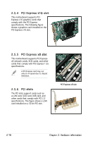
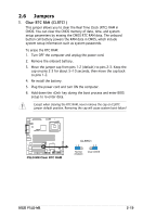
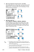
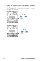
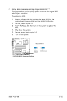
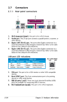
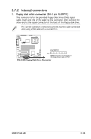
2. CPU fan pin selection (3-pin FM_CPU1, FM_CPU2) These jumpers allow you to connect either a 3-pin or a 4-pin fan cable plug to the CPU fan connectors (CPU_FAN1, CPU_FAN2). Set these jumpers to pins 1-2 if you are using a 3-pin fan cable plug, or to pins 2‑3 if you are using a 4-pin plug. R P5LD-MR FM_CPU2 2 3 4-pin fan (Default) 1 2 3-pin fan P5LD-MR FM CPU Setting FM_CPU1 2 3 4-pin fan (Default) 1 2 3-pin fan 3. USB device wake-up (3-pin USBPW12, USBPW34, USBPW56, USBPW78) Set these jumpers to +5V to wake up the computer from S1 sleep mode (CPU stopped, DRAM refreshed, system running in low power mode) using the connected USB devices. Set to +5VSB to wake up from S4 sleep mode (no power to CPU, DRAM in slow refresh, power supply in reduced power mode). USBPW12 R P5LD-MR USBPW12 12 23 +5V (Default) +5VSB USBPW34 12 23 USBPW34 USBPW56 USBPW78 P5LD-MR USB Device Wake-Up +5V (Default) +5VSB USBPW78 1 2 USBPW56 2 3 +5V (Default) +5VSB • The USB device wake-up feature requires a power supply that can provide 500mA on the +5VSB lead for each USB port; otherwise, the system would not power up. • If you are using Windows 2000, you need to install Service Pack 4 to wake up the system from S4 sleep mode. • The total current consumed must NOT exceed the power supply capability (+5VSB) whether under normal condition or in sleep mode. 2-20 Chapter 2: Hardware information
-
 1
1 -
2
-
3
-
4
-
5
-
6
-
7
-
8
-
9
-
10
-
11
-
12
-
13
-
14
-
15
-
16
-
17
-
18
-
19
-
20
-
21
-
22
-
23
-
24
-
25
-
26
-
27
-
28
-
29
-
30
-
31
-
32
-
33
-
34
-
 35
35 -
 36
36 -
 37
37 -
 38
38 -
 39
39 -
 40
40 -
 41
41 -
 42
42 -
 43
43 -
 44
44 -
 45
45 -
46
-
47
-
48
-
49
-
50
-
51
-
52
-
53
-
54
-
55
-
56
-
57
-
58
-
59
-
60
-
61
-
62
-
63
-
64
-
65
-
66
-
67
-
68
-
69
-
70
-
71
-
72
-
73
-
74
-
75
-
76
-
77
-
78
-
79
-
80
-
81
-
82
-
83
-
84
-
85
-
86
-
87
-
88
-
89
-
90
-
91
-
92
-
93
-
94
-
95
-
96
-
97
-
98
-
99
-
100
-
101
-
102
-
103
-
104
-
105
-
106
-
107
-
108
-
109
-
110
-
111
-
112
-
113
-
114
-
115
-
116
-
117
-
118
-
119
-
120
-
121
-
122
-
123
-
124
-
125
-
126
-
127
-
128
-
129
-
130
-
131
-
132
-
133
-
134
-
135
-
136
-
137
-
138
-
139
-
140
-
141
-
142
-
143
-
144
-
145
-
146
-
147
-
148
-
149
-
150
-
151
-
152
-
153
-
154
-
155
-
156
-
157
-
158
-
159
-
160
 |
 |
