Asus P5Q Deluxe User Manual - Page 91
NB GTL Voltage Reference [Auto], SB Voltage [Auto], PCIE SATA Voltage [Auto], Load-Line Calibration - chipset
 |
UPC - 610839162574
View all Asus P5Q Deluxe manuals
Add to My Manuals
Save this manual to your list of manuals |
Page 91 highlights
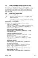
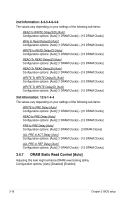
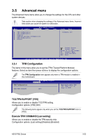
• The value [2.2V] of the NB Voltage item is supported only if the OV_NB jumper is enabled, otherwise the maximum voltage supported is [1.9V]. See 2. CPU / Northbridge overvoltage setting on page 2-19 for details. • Setting the CPU PLL Voltage, FSB Termination Voltage, DRAM Voltage and NB Voltage items to a high level may damage the chipset, memory module and CPU permanently. Proceed with caution. • Some values of the CPU PLL Voltage, FSB Termination Voltage, DRAM Voltage and NB Voltage items are labeled in different color, indicating the risk levels of high voltage settings. Refer to the table below for details. • The system may need better cooling system to work stably under high voltage settings. Blue CPU PLL Voltage 1.50V~1.78V FSB Termination Voltage 1.20V~1.38V DRAM Voltage 1.80V~1.98V NB Voltage 1.10V~1.26V Yellow 1.80V~2.00V 1.40V~1.90V 2.00V~2.20V 1.28V~1.40V Purple 2.02V~2.20V N/A 2.22V~2.40V 1.42V~1.58V Red 2.22V~2.78V N/A 2.42V~3.08V 1.60V~2.2V 3.4.19 NB GTL Voltage Reference [Auto] Allows you to set the Northbridge GTL voltage reference. Different ratio might enhance CPU overclocking ability. The values range from 0.370x to 0.760x with a 0.005x interval. 3.4.20 SB Voltage [Auto] Allows you to set the South Bridge voltage. The values range from 1.10V to 1.40V with a 0.10V interval. 3.4.21 PCIE SATA Voltage [Auto] Allows you to set the PCI Express SATA voltage. The values range from 1.50V to 1.80V with a 0.10V interval. 3.4.22 Load-Line Calibration [Auto] Allows you to select the CPU Load-Line mode. Set to [Disabled] to follow Intel specifications, or to [Enabled] to improve CPU VDroop directly. Configuration options: [Auto] [Disabled] [Enabled] 3.4.23 CPU Spread Spectrum [Auto] Set to [Disabled] to enhance FSB overclocking ability or [Auto] for EMI control. Configuration options: [Auto] [Disabled] ASUS P5Q Deluxe 3-21
-
 1
1 -
2
-
3
-
4
-
5
-
6
-
7
-
8
-
9
-
10
-
11
-
12
-
13
-
14
-
15
-
16
-
17
-
18
-
19
-
20
-
21
-
22
-
23
-
24
-
25
-
26
-
27
-
28
-
29
-
30
-
31
-
32
-
33
-
34
-
35
-
36
-
37
-
38
-
39
-
40
-
41
-
42
-
43
-
44
-
45
-
46
-
47
-
48
-
49
-
50
-
51
-
52
-
53
-
54
-
55
-
56
-
57
-
58
-
59
-
60
-
61
-
62
-
63
-
64
-
65
-
66
-
67
-
68
-
69
-
70
-
71
-
72
-
73
-
74
-
75
-
76
-
77
-
78
-
79
-
80
-
81
-
82
-
83
-
84
-
85
-
 86
86 -
 87
87 -
 88
88 -
 89
89 -
 90
90 -
 91
91 -
 92
92 -
 93
93 -
 94
94 -
 95
95 -
 96
96 -
97
-
98
-
99
-
100
-
101
-
102
-
103
-
104
-
105
-
106
-
107
-
108
-
109
-
110
-
111
-
112
-
113
-
114
-
115
-
116
-
117
-
118
-
119
-
120
-
121
-
122
-
123
-
124
-
125
-
126
-
127
-
128
-
129
-
130
-
131
-
132
-
133
-
134
-
135
-
136
-
137
-
138
-
139
-
140
-
141
-
142
-
143
-
144
-
145
-
146
-
147
-
148
-
149
-
150
-
151
-
152
-
153
-
154
-
155
-
156
-
157
-
158
-
159
-
160
-
161
-
162
-
163
-
164
-
165
-
166
-
167
-
168
-
169
-
170
-
171
-
172
-
173
-
174
-
175
-
176
-
177
-
178
-
179
-
180
-
181
-
182
-
183
-
184
-
185
-
186
-
187
-
188
-
189
-
190
-
191
-
192
 |
 |