Asus TRL-DLS TRL-DLS User Manual - Page 14
Hardware Setup
 |
View all Asus TRL-DLS manuals
Add to My Manuals
Save this manual to your list of manuals |
Page 14 highlights
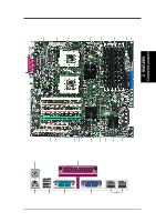
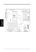
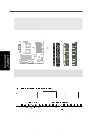
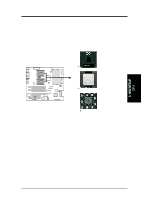
30.7cm (12.08in) 3. HARDWARE SETUP 3.1 TRL-DLS Motherboard Layout FLOPPY Secondary IDE SYSFAN2 Primary IDE CON12V DIMM Socket A3 (72-bit, 168-pin module) DIMM Socket B3 (72-bit, 168-pin module) DIMM Socket A2 (72-bit, 168-pin module) DIMM Socket B2 (72-bit, 168-pin module) DIMM Socket A1 (72-bit, 168-pin module) DIMM Socket B1 (72-bit, 168-pin module) PS/2 T: Mouse B: Keyboard USB1 USB2 COM1 ATX_POWER 33.2cm (13.07in) CPUFAN1 PARALLEL PORT Super I/O PGA 370 VGA RJ-45 ® TRL-DLS ServerWorks® CNB20 HESL North Bridge PGA 370 RJ-45 COM2 CPUFAN2 Intel Fast Ethernet Intel Fast Ethernet PCI1 (64-bit, 66MHz 3V) PCI2 (64-bit, 66MHz 3V) PCI3 (64-bit, 66MHz 3V) P1_66EN ServerWorks ® RCC CSB5 South Bridge CIOB20 I/O Bridge ATI RAGE XL VGA Controller PCI4 (64-bit, 66MHz 3V) PCI5 (32-bit, 33MHz 5V) WOL_CON PCI6 (32-bit, 33MHz 5V) ERMC CR2032 3V Lithium Cell CMOS Power WOR R216 ASUS ASIC with Hardware Monitor CHASSIS BUZZER SMB PANEL USBPORT 4Mbit Flash BIOS SYSFAN1 ADAPTEC SCSI Controller CHB-WIDE CHA-WIDE 34 1 68 35 NOTE: The SCSI and eRMC components are optional. These are grayed out in the above motherboard layout. 3. H/W SETUP Motherboard Layout 14 ASUS TRL-DLS User's Manual
-
 1
1 -
2
-
3
-
4
-
5
-
6
-
7
-
8
-
 9
9 -
 10
10 -
 11
11 -
 12
12 -
 13
13 -
 14
14 -
 15
15 -
 16
16 -
 17
17 -
 18
18 -
 19
19 -
20
-
21
-
22
-
23
-
24
-
25
-
26
-
27
-
28
-
29
-
30
-
31
-
32
-
33
-
34
-
35
-
36
-
37
-
38
-
39
-
40
-
41
-
42
-
43
-
44
-
45
-
46
-
47
-
48
-
49
-
50
-
51
-
52
-
53
-
54
-
55
-
56
-
57
-
58
-
59
-
60
-
61
-
62
-
63
-
64
-
65
-
66
-
67
-
68
-
69
-
70
-
71
-
72
-
73
-
74
-
75
-
76
-
77
-
78
-
79
-
80
-
81
-
82
-
83
-
84
-
85
-
86
 |
 |
