Asus TRL-DLS TRL-DLS User Manual - Page 25
H/w Setup
 |
View all Asus TRL-DLS manuals
Add to My Manuals
Save this manual to your list of manuals |
Page 25 highlights
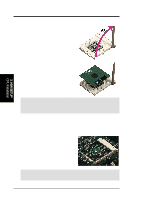
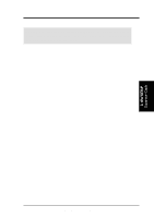
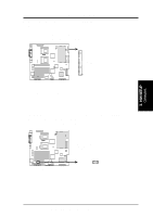
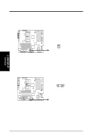
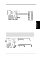
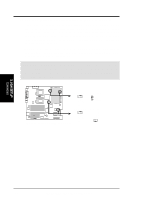
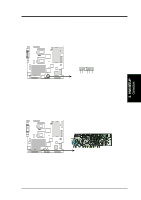
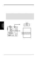
3. H/W SETUP Connectors 3. HARDWARE SETUP 2) Floppy Disk Drive Connector (34-1 pin FLOPPY) This connector supports the provided floppy drive ribbon cable. After connecting the single end to the board, connect the two plugs on the other end to the floppy drives. (Pin 5 is removed to prevent inserting in the wrong orientation when using ribbon cables with pin 5 plugged). ® TRL-DLS NOTE: Orient the red markings on the floppy ribbon cable to PIN 1. PIN 1 TRL-DLS Floppy Disk Drive Connector 3) Wake-On-LAN Connector (3-pin WOL_CON) This connector supports a LAN card with a Wake-On-LAN output. The connector powers up the system when a wakeup packet or signal is received through the LAN card. IMPORTANT: This feature requires that the BIOS item Onboard LAN Power Up is enabled (see 4.5.1 Power Up Control) and that your system has an ATX power supply with at least 720mA +5V standby power. ® TRL-DLS IMPORTANT: Requires an ATX power supply with at least 720mA +5 volt standby power WOL_CON Ground TRL-DLS Wake-On-LAN Connector PME +5 Volt Standby ASUS TRL-DLS User's Manual 25
-
 1
1 -
2
-
3
-
4
-
5
-
6
-
7
-
8
-
9
-
10
-
11
-
12
-
13
-
14
-
15
-
16
-
17
-
18
-
19
-
 20
20 -
 21
21 -
 22
22 -
 23
23 -
 24
24 -
 25
25 -
 26
26 -
 27
27 -
 28
28 -
 29
29 -
 30
30 -
31
-
32
-
33
-
34
-
35
-
36
-
37
-
38
-
39
-
40
-
41
-
42
-
43
-
44
-
45
-
46
-
47
-
48
-
49
-
50
-
51
-
52
-
53
-
54
-
55
-
56
-
57
-
58
-
59
-
60
-
61
-
62
-
63
-
64
-
65
-
66
-
67
-
68
-
69
-
70
-
71
-
72
-
73
-
74
-
75
-
76
-
77
-
78
-
79
-
80
-
81
-
82
-
83
-
84
-
85
-
86
 |
 |
