Asus TRL-DLS TRL-DLS User Manual - Page 33
ATX Power Switch / Soft-Off Switch Lead 2-pin
 |
View all Asus TRL-DLS manuals
Add to My Manuals
Save this manual to your list of manuals |
Page 33 highlights
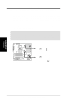
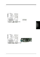
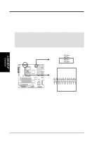
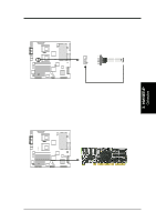
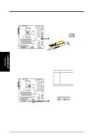
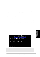
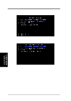
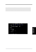
3. HARDWARE SETUP • NIC Activity LED Lead (2-pin) This shows the status of the NIC through a panel-mounted LED. • Status LED (2-pin) This shows the system status as programmed through the ASUS ASIC. • ATX Power Switch / Soft-Off Switch Lead (2-pin) The system power is controlled by a momentary switch connected to this lead. Pushing the button once switches the system between ON and SLEEP or ON and SOFT OFF, depending on your BIOS or OS setting. Pushing the switch while in the ON mode for more than 4 seconds turns the system off. The system power LED shows the status of the system power. • Reset Switch Lead (2-pin) This 2-pin connector connects to the case-mounted reset switch for rebooting your computer without having to turn off your power switch. This is a preferred method of rebooting to prolong the life of the system power supply. • System Power LED Lead (3-1 pin) This 3-1 pin connector connects to the system power LED that lights up when the system is powered on and blinks when it is in sleep or soft-off mode. This feature can be programmed through the ASUS ASIC. • NMI Lead (2-pin) This 2-pin connector connects to a panel button to allow a non-mask interrupt command to be sent to the operating system. • System Warning Speaker Lead (4-pin) This 4-pin connector connects to the case-mounted speaker. • HDD Activity LED (2-pin) This connector supplies power to the IDE and SCSI activity LED. Read and write activity by devices connected to the IDE and SCSI connectors cause this LED to light up. 3. H/W SETUP Connectors ASUS TRL-DLS User's Manual 33
-
 1
1 -
2
-
3
-
4
-
5
-
6
-
7
-
8
-
9
-
10
-
11
-
12
-
13
-
14
-
15
-
16
-
17
-
18
-
19
-
20
-
21
-
22
-
23
-
24
-
25
-
26
-
27
-
 28
28 -
 29
29 -
 30
30 -
 31
31 -
 32
32 -
 33
33 -
 34
34 -
 35
35 -
 36
36 -
 37
37 -
 38
38 -
39
-
40
-
41
-
42
-
43
-
44
-
45
-
46
-
47
-
48
-
49
-
50
-
51
-
52
-
53
-
54
-
55
-
56
-
57
-
58
-
59
-
60
-
61
-
62
-
63
-
64
-
65
-
66
-
67
-
68
-
69
-
70
-
71
-
72
-
73
-
74
-
75
-
76
-
77
-
78
-
79
-
80
-
81
-
82
-
83
-
84
-
85
-
86
 |
 |
