Belkin F1DP108A User Manual - Page 30
Connecting the Servers - power supply
 |
UPC - 722868564004
View all Belkin F1DP108A manuals
Add to My Manuals
Save this manual to your list of manuals |
Page 30 highlights
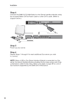
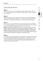
section Installation Connecting the Servers: 1 Step 1 Connect all servers to the primary and secondary KVM switches. Refer to 2 the "Connecting Servers to the SMB CAT5 KVM Switch" section on page 17 for instructions. 3 Step 2 4 Make sure that the power adapter is connected to the primary KVM switch and that the KVM switch is powered on. You should see the primary KVM switch light up and display the digits "00", indicating its BANK address. 5 Step 3 6 Power up the secondary KVM switches sequentially, beginning with BANK 01, by connecting each unit's power supply. Each KVM switch should display its corresponding BANK address number as it is powered up. 7 NOTE: If the SMB CAT5 KVM Switches do not enumerate correctly, reset the primary KVM switch (BANK 00) by simultaneously pressing the "BANK +" and 8 "BANK -" buttons. You can also reset the primary KVM switch to detect newly added secondary KVM switches. If the KVM switches still do not enumerate correctly, check that all KVM switches have the correct BANK address assigned to them and that all daisy-chain cables are connected properly. Step 4 Verify that the primary KVM switch has detected all secondary KVM switches by scrolling through the BANKS using the "BANK +" and "BANK -" buttons. If all secondary KVM switches are detected properly, the LED display on the primary KVM switch will register and display the BANK address of the attached secondary KVM switch. 27
-
 1
1 -
2
-
3
-
4
-
5
-
6
-
7
-
8
-
9
-
10
-
11
-
12
-
13
-
14
-
15
-
16
-
17
-
18
-
19
-
20
-
21
-
22
-
23
-
24
-
 25
25 -
 26
26 -
 27
27 -
 28
28 -
 29
29 -
 30
30 -
 31
31 -
 32
32 -
 33
33 -
 34
34 -
 35
35 -
36
-
37
-
38
-
39
-
40
-
41
-
42
-
43
-
44
-
45
-
46
-
47
-
48
-
49
-
50
-
51
-
52
-
53
-
54
-
55
-
56
-
57
-
58
-
59
-
60
-
61
-
62
-
63
-
64
-
65
-
66
-
67
-
68
-
69
-
70
-
71
-
72
-
73
-
74
-
75
-
76
-
77
-
78
-
79
-
80
-
81
-
82
-
83
-
84
-
85
-
86
-
87
-
88
-
89
-
90
-
91
-
92
-
93
-
94
-
95
-
96
-
97
-
98
-
99
-
100
-
101
-
102
-
103
-
104
-
105
-
106
-
107
-
108
-
109
-
110
-
111
-
112
-
113
-
114
-
115
-
116
-
117
-
118
-
119
-
120
-
121
-
122
-
123
-
124
-
125
-
126
-
127
-
128
-
129
-
130
-
131
-
132
-
133
-
134
-
135
-
136
-
137
-
138
-
139
-
140
-
141
-
142
-
143
-
144
-
145
-
146
-
147
-
148
-
149
-
150
-
151
-
152
-
153
-
154
-
155
-
156
-
157
-
158
-
159
-
160
-
161
-
162
-
163
-
164
-
165
-
166
-
167
-
168
-
169
-
170
-
171
-
172
-
173
-
174
-
175
-
176
-
177
-
178
-
179
-
180
-
181
-
182
-
183
-
184
-
185
-
186
-
187
-
188
-
189
-
190
-
191
-
192
-
193
-
194
-
195
-
196
-
197
-
198
-
199
-
200
-
201
-
202
-
203
-
204
-
205
-
206
-
207
-
208
-
209
-
210
-
211
-
212
-
213
-
214
-
215
-
216
-
217
-
218
-
219
-
220
-
221
-
222
-
223
-
224
-
225
-
226
-
227
-
228
-
229
-
230
-
231
-
232
-
233
-
234
-
235
-
236
-
237
-
238
-
239
-
240
-
241
-
242
-
243
-
244
-
245
-
246
-
247
-
248
-
249
-
250
-
251
-
252
-
253
-
254
-
255
-
256
-
257
-
258
-
259
-
260
-
261
-
262
-
263
-
264
-
265
-
266
-
267
-
268
-
269
-
270
-
271
-
272
-
273
-
274
-
275
-
276
-
277
-
278
-
279
-
280
-
281
-
282
-
283
-
284
-
285
-
286
-
287
-
288
-
289
-
290
-
291
-
292
-
293
-
294
-
295
-
296
-
297
-
298
-
299
-
300
-
301
-
302
-
303
-
304
-
305
-
306
 |
 |