Bosch DHR-1600A-150A Installation Manual
Bosch DHR-1600A-150A Manual
 |
View all Bosch DHR-1600A-150A manuals
Add to My Manuals
Save this manual to your list of manuals |
Bosch DHR-1600A-150A manual content summary:
- Bosch DHR-1600A-150A | Installation Manual - Page 1
Divar XF Digital Hybrid Recorder en Installation manual - Bosch DHR-1600A-150A | Installation Manual - Page 2
- Bosch DHR-1600A-150A | Installation Manual - Page 3
4.7 Hardware setup Desktop installation Rack mounting Hard disk installation Mounting instructions Camera connections Audio connections Monitor connections VGA CVBS Y/C Monitor streaming connection Bosch Security Systems Installation manual Table of Contents | en 3 7 7 8 8 10 12 13 13 13 13 - Bosch DHR-1600A-150A | Installation Manual - Page 4
5.10 5.10.1 5.10.2 5.10.3 5.10.4 Operating instructions Front panel controls Keys Indicators Mouse Controls Viewing pictures Monitor A Monitor /date Time Server Video & Audio F.01U.135.429 | 2.5 | 2009.08 Installation manual Divar XF 28 28 29 30 30 32 32 34 34 34 35 35 35 37 Bosch Security Systems - Bosch DHR-1600A-150A | Installation Manual - Page 5
Monitor Streaming Storage Status Settings Service Users General Administrator User 1 - 7 System Service Serial ports Licenses Logging log on Menu structure differences Introducing the main window Overview button Bosch Security Systems Installation manual Table of Contents | en 5 56 57 58 58 58 - Bosch DHR-1600A-150A | Installation Manual - Page 6
7.4 8 8.1 8.2 8.3 9 9.1 9.1.1 9.1.2 9.1.3 9.1.4 9.1.5 Logbook button Settings button Service button Help button Logout button Using the control buttons Menu default values Quick install menu defaults 83 85 85 85 85 86 F.01U.135.429 | 2.5 | 2009.08 Installation manual Bosch Security Systems - Bosch DHR-1600A-150A | Installation Manual - Page 7
the manufacturer's instructions have been Power disconnect - Servicing - Do not attempt to service this unit yourself. Opening or removing covers may expose you to dangerous voltage or other hazards. Refer all servicing to qualified service personnel. Bosch Security Systems Installation manual - Bosch DHR-1600A-150A | Installation Manual - Page 8
exhibits a distinct change in performance; - unit does not operate normally when the user correctly follows the operating instructions. 14. Replacement parts - Be sure the service technician uses replacement parts specified by the manufacturer, or that have the same characteristics as the original - Bosch DHR-1600A-150A | Installation Manual - Page 9
Divar XF Safety | en 9 disconnect device for switching off the voltage to the unit. Battery replacement - For qualified service personnel only - A lithium battery is located inside the unit enclosure. To avoid danger of explosion, replace the battery as per instructions. Replace only with the same - Bosch DHR-1600A-150A | Installation Manual - Page 10
Alternately grounding plug. Moving - Disconnect the power before moving accessible disconnect device specified operating temperatures, disconnect the power cord, wait For detailed instructions, please ; therefore, Bosch Security Systems cannot digital information, Bosch Security Systems instructions, - Bosch DHR-1600A-150A | Installation Manual - Page 11
d'installation ou d'utilisation non conforme aux instructions, engendrer des interférences nuisibles au niveau : How to Identify and Resolve Radio-TV Interference Problems (Comment identifier et résoudre les problèmes d'interf Bosch Security Systems Installation manual F.01U.135.429 | 2.5 | 2009. - Bosch DHR-1600A-150A | Installation Manual - Page 12
. NOTE! This manual has been compiled with great care and the information it contains has been thoroughly verified. The text was complete and correct at the time of printing. The ongoing development of the products may mean that the content of the user guide can change without notice. Bosch Security - Bosch DHR-1600A-150A | Installation Manual - Page 13
operated and programmed via the front panel control keys, mouse, and the Manuals Four manuals are supplied: - Installation manual - a detailed description for installers on how to install the product. - Quick Installation guide Bosch Security Systems Installation manual F.01U.135.429 | 2.5 | 2009.08 - Bosch DHR-1600A-150A | Installation Manual - Page 14
- Support for guide - Divar XF operation manual - Divar XF Control Center and Archive Player operation manual - Installation manual (this manual service and testing purposes) - Rack mounting kit - A CD-ROM containing the software and manuals F.01U.135.429 | 2.5 | 2009.08 Installation manual Bosch - Bosch DHR-1600A-150A | Installation Manual - Page 15
Cameras with 1 Vpp composite video outputs - IP cameras (see datasheet for supported models) - Amplified microphone(s) - Audio amplifier with speaker(s) - Video coaxial Tool applications - Pan/tilt/zoom control units Bosch Security Systems Installation manual F.01U.135.429 | 2.5 | 2009.08 - Bosch DHR-1600A-150A | Installation Manual - Page 16
16 en | Introduction Divar XF F.01U.135.429 | 2.5 | 2009.08 Installation manual Bosch Security Systems - Bosch DHR-1600A-150A | Installation Manual - Page 17
240 VAC x16* 1 AutoDome Figure 3.1 Back panel connections Primary connections 1. Connect the cameras to the 4. Connect monitor B to the BNC, Y/C, or VGA (supporting 1024x768) output MON B. 5. Connect up to 16 audio Bosch Security Systems Installation manual F.01U.135.429 | 2.5 | 2009.08 - Bosch DHR-1600A-150A | Installation Manual - Page 18
A. 3. Click Configuration and then Quick install. Navigating Use the supplied USB mouse. Alternatively, use the following front panel keys: - Use the enter button to select a submenu or item. - Use menu - International F.01U.135.429 | 2.5 | 2009.08 Installation manual Bosch Security Systems - Bosch DHR-1600A-150A | Installation Manual - Page 19
2 - Green - Profile 3 - Pink - Profile 4 - Light blue- Profile 5 - Brown - Profile 6 Click Overwrite to start making changes. - Select at which day the week should start and end. Bosch Security Systems Installation manual F.01U.135.429 | 2.5 | 2009.08 - Bosch DHR-1600A-150A | Installation Manual - Page 20
previously made, click Overwrite to replace them with Quick install settings. Click Next to move to the next tab. F.01U.135.429 | 2.5 | 2009.08 Installation manual Bosch Security Systems - Bosch DHR-1600A-150A | Installation Manual - Page 21
bandwidth by entering a value between 0.1 and 100 Mbps for the bandwidth limit. MAC address The MAC address is read only. Cable connected Shows cable status. Bosch Security Systems Installation manual F.01U.135.429 | 2.5 | 2009.08 - Bosch DHR-1600A-150A | Installation Manual - Page 22
22 en | Quick install Divar XF F.01U.135.429 | 2.5 | 2009.08 Installation manual Bosch Security Systems - Bosch DHR-1600A-150A | Installation Manual - Page 23
the four cross head screws (two on each side) located near the front panel on the right and left side of the unit. 2. Secure the supplied and following the rack manufacturer's instructions. Figure 4.2 Securing the rack mounting bracket Bosch Security Systems Installation manual F.01U.135.429 | - Bosch DHR-1600A-150A | Installation Manual - Page 24
instructions panel to the right until it is free. 3. Place the front panel on top of the unit, taking care not to strain the flat cable. If there is no room on top of the unit, disconnect the flat cable and set the front panel aside. F.01U.135.429 | 2.5 | 2009.08 Installation manual Bosch - Bosch DHR-1600A-150A | Installation Manual - Page 25
is in place. 3. Refasten the two captive cross head screws to the front panel. Camera connections Connect cameras to the Video in connectors on the back of the Video out connector. The camera input connectors are auto- Bosch Security Systems Installation manual F.01U.135.429 | 2.5 | 2009.08 - Bosch DHR-1600A-150A | Installation Manual - Page 26
6 7 8 Video out Figure 4.5 Eight video inputs with loop-through outputs Audio connections The DivarXF supports up to 16 audio inputs and 4 audio outputs. Connect using audio cable with RCA compatible connectors LCD(s). F.01U.135.429 | 2.5 | 2009.08 Installation manual Bosch Security Systems - Bosch DHR-1600A-150A | Installation Manual - Page 27
To connect a monitor in a remote streaming configuration, connect the CVBS monitor output to a video input. Then connect the monitor to the corresponding loop-through connector. Bosch Security Systems Installation manual F.01U.135.429 | 2.5 | 2009.08 - Bosch DHR-1600A-150A | Installation Manual - Page 28
connection RS232 COM port connections The RS232 COM ports are used to connect a PC to the unit for service purposes. Use a nullmodem cable to connect the serial port of the PC to the unit. The Baud and the appropriate power F.01U.135.429 | 2.5 | 2009.08 Installation manual Bosch Security Systems - Bosch DHR-1600A-150A | Installation Manual - Page 29
: ± 2.8 V maximum, inputs have transient overvoltage protection Ethernet port details: EEE 802.3/802.3u - 100Base-TX/10Base-T physical layer Auto negotiation: 10/100, full/half duplex Bosch Security Systems Installation manual F.01U.135.429 | 2.5 | 2009.08 - Bosch DHR-1600A-150A | Installation Manual - Page 30
port Connect third-party controllable cameras to the unit for pan, tilt, and zoom control. The Pelco D protocol is supported with the following baud settings: 2400 baud 1 start bit 8 data bits 1 stop bit no parity - | + . F.01U.135.429 | 2.5 | 2009.08 Installation manual Bosch Security Systems - Bosch DHR-1600A-150A | Installation Manual - Page 31
ch. 4 (plus) System ground/cable shield Biphase control ch. 5 (minus) Biphase control ch. 5 (plus) System ground/cable shield Table 4.6 Control port - 15-pole D-type socket Bosch Security Systems Installation manual F.01U.135.429 | 2.5 | 2009.08 - Bosch DHR-1600A-150A | Installation Manual - Page 32
port 16 if it is connected to channel 16). USB connectors Four USB connectors are located at the rear panel of the unit. For convenience, one USB port is located on the front of the unit to connect : AWG 26-16 (0.13-1.5 mm2) F.01U.135.429 | 2.5 | 2009.08 Installation manual Bosch Security Systems - Bosch DHR-1600A-150A | Installation Manual - Page 33
2 output pole 1 Relay 2 output pole 2 Relay 3 output pole 1 Relay 3 output pole 2 Relay 4 output pole 1 Relay 4 output pole 2 Chassis ground Table 4.8 External I/O - 25-pole D-type socket Bosch Security Systems Installation manual F.01U.135.429 | 2.5 | 2009.08 - Bosch DHR-1600A-150A | Installation Manual - Page 34
voltage. Risk of electric shock. Do not open the top cover or attempt to service the unit. No user serviceable parts inside. Refer all servicing to qualified service personnel. Opening the top cover will void the warranty! F.01U.135.429 | 2.5 | 2009.08 Installation manual Bosch Security Systems - Bosch DHR-1600A-150A | Installation Manual - Page 35
instructions | en 35 Operating instructions These instructions explain the purpose of the front panel cameo is shown full screen when viewing video in multiscreen mode ESC key - press to return to previous level or to exit Bosch Security Systems Installation manual F.01U.135.429 | 2.5 | 2009.08 - Bosch DHR-1600A-150A | Installation Manual - Page 36
36 en | Operating instructions Divar XF OSD key - press to view date/time and camera information, date/time only, or none Search key - press up the forward playback rate - in pause mode, press to step forward one frame F.01U.135.429 | 2.5 | 2009.08 Installation manual Bosch Security Systems - Bosch DHR-1600A-150A | Installation Manual - Page 37
instructions by the front panel can, alternatively, be accessed using ESC to remove it from the screen. Figure 5.2 On-screen button panel The buttons and indicators of the on-screen button panel work the same as the keys and indicators on the front panel. Bosch Security Systems Installation manual - Bosch DHR-1600A-150A | Installation Manual - Page 38
instructions A: 1. Check that the light on the front panel is lit. 2. If is not lit, press the monitor B: 1. Check that the light on the front panel is lit. 2. If is not lit, press the 3 4 5 6 7 8 9 Figure 5.3 Divar XF supports single, quad, 3x3, and 4x4 screen viewing The multiscreen - Bosch DHR-1600A-150A | Installation Manual - Page 39
Divar XF Operating instructions | en 39 Multiscreen To active cameo. 2. Press the freeze key again to return to live viewing. Alternatively, right click and select Freeze or Unfreeze from the context menu using the mouse . Bosch Security Systems Installation manual F.01U.135.429 | 2.5 | 2009.08 - Bosch DHR-1600A-150A | Installation Manual - Page 40
40 en | Operating instructions Divar XF 5.4 5.4.1 5.4.2 5.4.3 Zoom To zoom in on zoom key again to return to a full picture and leave the zoom mode. Alternatively, right click and select Zoom or Exit zoom to enable or disable zoom mode 2.5 | 2009.08 Installation manual Bosch Security Systems - Bosch DHR-1600A-150A | Installation Manual - Page 41
Divar XF 5.5 Operating instructions | en 41 Overview of the menu system The menu gives access to several functions to help you use the unit. Access to some menu items is password protected. There are three ways of accessing the menu system: - via the front panel keys, - a USB mouse, or - a Intuikey - Bosch DHR-1600A-150A | Installation Manual - Page 42
Operating instructions Help Divar XF The Help function displays a help text. Exit 5.5.1 5.5.2 5.5.3 5.6 Click to log off. Access using the front panel keys To open the menu, press the menu key. - The top menu appears on monitor A. To move through a menu or list, use the arrow panel. To select - Bosch DHR-1600A-150A | Installation Manual - Page 43
search Operating instructions | en 43 Enter the start date and time and click OK to start playback. Playback of the displayed cameos starts. 5.6.2 Figure 5.6 Search by date and time Event search Figure 5.7 Search Events menu - Search options Bosch Security Systems Installation manual F.01U - Bosch DHR-1600A-150A | Installation Manual - Page 44
44 en | Operating instructions Divar XF Search criteria - Under Channels, check the camera inputs to search for (highlight the un-numbered box the selected recording. - Press the escape key to return to the search menu. F.01U.135.429 | 2.5 | 2009.08 Installation manual Bosch Security Systems - Bosch DHR-1600A-150A | Installation Manual - Page 45
Divar XF 5.7 Export Operating instructions | en 45 Figure 5.9 Top menu - Export video The export menu is accessed from the select it and click Change. 1. To remove a video segment from the list, select it and click Remove. Bosch Security Systems Installation manual F.01U.135.429 | 2.5 | 2009.08 - Bosch DHR-1600A-150A | Installation Manual - Page 46
46 en | Operating instructions Divar XF 5.8 The archive list is saved until archiving is carried out. Video segments that have been partially or gray). Multiscreens Select those multiscreen views that you wish to see. F.01U.135.429 | 2.5 | 2009.08 Installation manual Bosch Security Systems - Bosch DHR-1600A-150A | Installation Manual - Page 47
Divar XF Operating instructions | en 47 5.9 Figure 5.12 Configure monitors menu - Sequence Sequence Select the length of System information menu contains two submenus: - Status - opens a menu to view status information. Bosch Security Systems Installation manual F.01U.135.429 | 2.5 | 2009.08 - Bosch DHR-1600A-150A | Installation Manual - Page 48
48 en | Operating instructions 5.9.1 - Logbook - opens a menu to firmware version, serial number, and other version-related information for service purposes. Storage status The storage status tab displays information on disk F.01U.135.429 | 2.5 | 2009.08 Installation manual Bosch Security Systems - Bosch DHR-1600A-150A | Installation Manual - Page 49
Divar XF 5.9.2 Operating instructions | en 49 critical level, the unit automatically shuts down. To restart the unit, disconnect the power cord, wait for at least 30 seconds, and then reconnect various system events. Bosch Security Systems Installation manual F.01U.135.429 | 2.5 | 2009.08 - Bosch DHR-1600A-150A | Installation Manual - Page 50
50 en | Operating instructions Divar XF 5.10 Figure 5.15 Logbook menu - Logbook filter - Enter start and end times. - Make a selection of which images are displayed on the monitors without requiring user intervention. F.01U.135.429 | 2.5 | 2009.08 Installation manual Bosch Security Systems - Bosch DHR-1600A-150A | Installation Manual - Page 51
Divar XF 5.10.1 Operating instructions | en 51 Alarms An alarm can cause the unit to react as follows: - A beeper sounds. - A status enabled, the beeper and the alarm and switch off after the dwell time. indicators, Bosch Security Systems Installation manual F.01U.135.429 | 2.5 | 2009.08 - Bosch DHR-1600A-150A | Installation Manual - Page 52
52 en | Operating instructions Divar XF 5.10.2 5.10.3 5.10.4 Contact inputs cameo. An alarm status message is displayed. - The motion indicator on the front panel flashes. Video loss alarm If the loss of a video signal causes an alarm: | 2.5 | 2009.08 Installation manual Bosch Security Systems - Bosch DHR-1600A-150A | Installation Manual - Page 53
1-8 (or 1-16 depending on model) Profiles 1 to 6 - General - Contact - Motion - Video loss Setup IP range Monitor streaming Status Settings Service General Administrator Users 1 to 7 Service Serial ports Licenses Logging Bosch Security Systems Installation manual F.01U.135.429 | 2.5 | 2009.08 - Bosch DHR-1600A-150A | Installation Manual - Page 54
54 en | Advanced configuration menu 6.1 6.1.1 International Language Divar XF Figure 6.1 International menu - Language - Select your Language from the drop-down list. - Select the preferred Temperature unit. F.01U.135.429 | 2.5 | 2009.08 Installation manual Bosch Security Systems - Bosch DHR-1600A-150A | Installation Manual - Page 55
first. - Enter the actual Date. - Set Daylight Saving to Automatic to enable it. Set to Manual and fill in the day, month, and time of both Start and End time, and the Offset Click Synchronize to start time synchronization. Bosch Security Systems Installation manual F.01U.135.429 | 2.5 | 2009.08 - Bosch DHR-1600A-150A | Installation Manual - Page 56
every four days) can only change the clock by a maximum of 10 minutes. Note: If you synchronize manually and the actual time is put back by more than 10 minutes, all video content on the hard corresponding audio inputs. F.01U.135.429 | 2.5 | 2009.08 Installation manual Bosch Security Systems - Bosch DHR-1600A-150A | Installation Manual - Page 57
automatically adjust the contrast for the video input. - Contrast - can be set manually with the slider if Auto contrast is disabled. Enable audio input - Enable the datasheet for a list of supported IP cameras and encoders. Bosch Security Systems Installation manual F.01U.135.429 | 2.5 | 2009.08 - Bosch DHR-1600A-150A | Installation Manual - Page 58
number. The selected profile is highlighted. 2. Click Edit selected profile name to edit the name of the selected profile. F.01U.135.429 | 2.5 | 2009.08 Installation manual Bosch Security Systems - Bosch DHR-1600A-150A | Installation Manual - Page 59
an contact input event - Motion recording - activated upon a motion event 3. Choose an individual input channel to configure the settings for recording its video and audio. Bosch Security Systems Installation manual F.01U.135.429 | 2.5 | 2009.08 - Bosch DHR-1600A-150A | Installation Manual - Page 60
if you wish to copy several camera inputs within the From profile. 2. Select the profile number to copy from. F.01U.135.429 | 2.5 | 2009.08 Installation manual Bosch Security Systems - Bosch DHR-1600A-150A | Installation Manual - Page 61
three modes available: - No override (default) - Follows: the profile override lasts for as long as the input is active (no override duration can be set). Bosch Security Systems Installation manual F.01U.135.429 | 2.5 | 2009.08 - Bosch DHR-1600A-150A | Installation Manual - Page 62
Trigger level to set the motion sensitivity. If the motion indicator exceeds the trigger level, a motion event is generated. F.01U.135.429 | 2.5 | 2009.08 Installation manual Bosch Security Systems - Bosch DHR-1600A-150A | Installation Manual - Page 63
Figure 6.8 Event menu - General General Auto acknowledge alarms - Enable when alarms should be acknowledged automatically. By default, an alarm must be manually acknowledged. Alarm dwell time - Set between 1 and 59 seconds to select the period during which the output relay and the beeper remain - Bosch DHR-1600A-150A | Installation Manual - Page 64
each video channel in turn. - Check the Enabled box for each video channel if video loss should activate a trigger. F.01U.135.429 | 2.5 | 2009.08 Installation manual Bosch Security Systems - Bosch DHR-1600A-150A | Installation Manual - Page 65
of the unit. - Enable DHCP to have IP address, subnet mask, and default gateway assigned automatically by the network server. The actual values are displayed. Bosch Security Systems Installation manual F.01U.135.429 | 2.5 | 2009.08 - Bosch DHR-1600A-150A | Installation Manual - Page 66
: Disable the recording of a channel used for monitor streaming in the Recording tab. Figure 6.10 Network menu - Monitor streaming F.01U.135.429 | 2.5 | 2009.08 Installation manual Bosch Security Systems - Bosch DHR-1600A-150A | Installation Manual - Page 67
settings to write protect a disk and to add/remove it from the active disk set. Service - Delete recording until... - opens a submenu to delete video older than a specified date. Password that can be up to 12 characters. Bosch Security Systems Installation manual F.01U.135.429 | 2.5 | 2009.08 - Bosch DHR-1600A-150A | Installation Manual - Page 68
file to a USB memory device when connected. This is for service purposes only. - Export system configuration saves a copy of the via: https://activation.boschsecurity.com The license number and instructions on how to obtain the activation key can be .08 Installation manual Bosch Security Systems - Bosch DHR-1600A-150A | Installation Manual - Page 69
Divar XF 6.11.4 Logging Select the items to be logged. - Log contacts - Log motion - Log remote access Advanced configuration menu | en 69 Bosch Security Systems Installation manual F.01U.135.429 | 2.5 | 2009.08 - Bosch DHR-1600A-150A | Installation Manual - Page 70
70 en | Advanced configuration menu Divar XF F.01U.135.429 | 2.5 | 2009.08 Installation manual Bosch Security Systems - Bosch DHR-1600A-150A | Installation Manual - Page 71
XF itself, the Configuration Tool offers a very user-friendly alternative. It also allows configuration settings to be saved on and double click it. 3. Follow the instructions on the screen and select the install Configuration Bosch Security Systems Installation manual F.01U.135.429 | 2.5 | 2009.08 - Bosch DHR-1600A-150A | Installation Manual - Page 72
the list, select the Divar XF to delete. 2. Click Delete - The selected Divar XF is removed from the list. F.01U.135.429 | 2.5 | 2009.08 Installation manual Bosch Security Systems - Bosch DHR-1600A-150A | Installation Manual - Page 73
these buttons changes the contents of the center pane. The buttons in the top pane are control buttons that give direct access to various tasks. Bosch Security Systems Installation manual F.01U.135.429 | 2.5 | 2009.08 - Bosch DHR-1600A-150A | Installation Manual - Page 74
the parameters for that page item. - Select the values you want for the parameters. - These values are updated immediately. F.01U.135.429 | 2.5 | 2009.08 Installation manual Bosch Security Systems - Bosch DHR-1600A-150A | Installation Manual - Page 75
the settings. Print To print the complete contents of the page or list when the Overview or Service page is active: 1. Click Print to print the current settings. 2. Click OK to print. action. Up to 100 actions can be undone. Bosch Security Systems Installation manual F.01U.135.429 | 2.5 | 2009.08 - Bosch DHR-1600A-150A | Installation Manual - Page 76
on the active page to their default Click Refresh to refresh the content of the current page settings only. F.01U.135.429 | 2.5 | 2009.08 Installation manual Bosch Security Systems - Bosch DHR-1600A-150A | Installation Manual - Page 77
.00-18.00 08.00-18.00 4CIF Medium 6.25 IPS 4CIF High 25 IPS 4CIF High 25 IPS DIVAR XF Enabled 0.0.0.0 0.0.0.0 0.0.0.0 0.0.0.0 100 Mbps Reset N N N N N N N Y Y Y Y Y Y Y Y Y Y Y Y N N N N N N N Bosch Security Systems Installation manual F.01U.135.429 | 2.5 | 2009.08 - Bosch DHR-1600A-150A | Installation Manual - Page 78
IP address Default value English Celsius GMT+1 West Europe 24-hour 0:00 DD-MM-YYYY 1-1-2008 Automatic Disabled 0.0.0.0 Reset N N N N N N N N N N N N N F.01U.135.429 | 2.5 | 2009.08 Installation manual Bosch Security Systems - Bosch DHR-1600A-150A | Installation Manual - Page 79
6.25 IPS Disabled Medium Fixed duration 30 seconds 4CIF High 25 IPS Disabled Medium Fixed duration 30 seconds 4CIF High 25 IPS Disabled Medium Reset Y Y Y Y Y Y Y N N N N N N Y Y Y Y Y Y Y Y Y Y Y Y Y Y Y Y Y Y Y Y Y Y Y Bosch Security Systems Installation manual F.01U.135.429 | 2.5 | 2009.08 - Bosch DHR-1600A-150A | Installation Manual - Page 80
24 Network Setup Video loss 1...24 IP range Storage Monitor streaming Status Settings Service Setting Default value Reset Contact Inputs NC None Y Relay Outputs NC None NA Override after Disk full set Y NA F.01U.135.429 | 2.5 | 2009.08 Installation manual Bosch Security Systems - Bosch DHR-1600A-150A | Installation Manual - Page 81
User 1..7 Access rights Control rights System Service Serial ports Licenses Logging Menu default values remote access Enabled Enabled Enabled Reset Y Y Y NA Y Y Y Y Y Y Y Y Y Y Y Y Y Y Y NA N N Y N Y Y Y Y NA Y Y Y Bosch Security Systems Installation manual F.01U.135.429 | 2.5 | 2009.08 - Bosch DHR-1600A-150A | Installation Manual - Page 82
82 en | Menu default values Divar XF F.01U.135.429 | 2.5 | 2009.08 Installation manual Bosch Security Systems - Bosch DHR-1600A-150A | Installation Manual - Page 83
± 10% PAL/NTSC auto-detect 720 x 576 PAL - 720 x 484 NTSC Automatic adjustment or manual adjustment of gain for each video input 1.5 - 6 times H.264 Audio Inputs Outputs Sample rate Compression 11 V-12.6 V at max 400 mA Bosch Security Systems Installation manual F.01U.135.429 | 2.5 | 2009.08 - Bosch DHR-1600A-150A | Installation Manual - Page 84
, 7.5, 3.75, 1 704 x 576 PAL - 704 x 480 NTSC 704 x 288 PAL - 704 x 240 NTSC 352 x 288 PAL - 352 x 240 NTSC F.01U.135.429 | 2.5 | 2009.08 Installation manual Bosch Security Systems - Bosch DHR-1600A-150A | Installation Manual - Page 85
500GB storage expansion kit 1TB storage expansion kit License for RAID 4 storage LTC 2605/91 License for 4 IP cameras License for 8 IP cameras LTC 8782 Bosch Security Systems Installation manual F.01U.135.429 | 2.5 | 2009.08 - Bosch DHR-1600A-150A | Installation Manual - Page 86
addition, ensure that the camera is mounted so that it does not shake due to wind or other influences. F.01U.135.429 | 2.5 | 2009.08 Installation manual Bosch Security Systems - Bosch DHR-1600A-150A | Installation Manual - Page 87
- Bosch DHR-1600A-150A | Installation Manual - Page 88
Bosch Security Systems Robert-Koch-Straße 100 D-85521 Ottobrunn Germany Telefon 089 6290-0 Fax 089 6290-1020 www.boschsecurity.com © Bosch Security Systems, 2009
-
 1
1 -
 2
2 -
 3
3 -
 4
4 -
 5
5 -
 6
6 -
 7
7 -
8
-
9
-
10
-
11
-
12
-
13
-
14
-
15
-
16
-
17
-
18
-
19
-
20
-
21
-
22
-
23
-
24
-
25
-
26
-
27
-
28
-
29
-
30
-
31
-
32
-
33
-
34
-
35
-
36
-
37
-
38
-
39
-
40
-
41
-
42
-
43
-
44
-
45
-
46
-
47
-
48
-
49
-
50
-
51
-
52
-
53
-
54
-
55
-
56
-
57
-
58
-
59
-
60
-
61
-
62
-
63
-
64
-
65
-
66
-
67
-
68
-
69
-
70
-
71
-
72
-
73
-
74
-
75
-
76
-
77
-
78
-
79
-
80
-
81
-
82
-
83
-
84
-
85
-
86
-
87
-
88
 |
 |
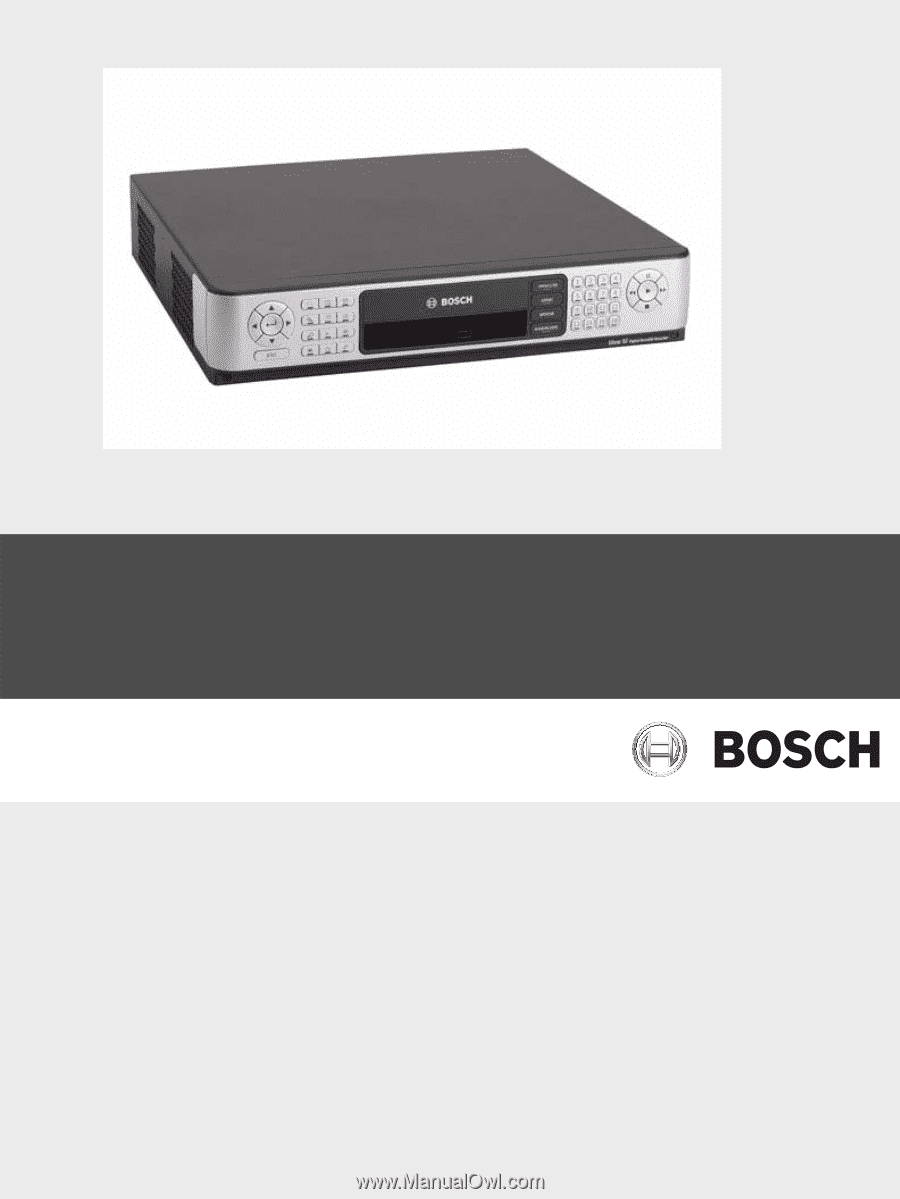
Divar XF
Digital Hybrid Recorder
en
Installation manual