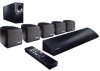
Bose Companion Surround Sound Owner's guide - Page 8
Connecting, speakers, module, controller, remote, sensor,
 |
View all Bose Companion Surround Sound manuals
Add to My Manuals
Save this manual to your list of manuals |
Page 8 highlights
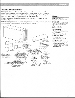
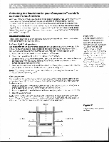
ii Connecting the cube speakers to the bass module Each speaker cable contains two wires. The wire marked with a red collar is positive (+) and the plain one is negative (-). These wires match the positive (red) and negative (black) terminals on the back of each speaker. To lengthen the cable, use standard RCA extension cables or splice in 18-gauge or thicker cord (connecting + to + and - to -). To purchase cables, see your dealer, electronics store, or call Bose° customer service. Note: The surround cables are joined together for your convenience, providing an easy-touse cable for connecting the surround speakers. To run the cables in different directions from the bass module, simply pull apart the cables as needed. 1. Match the correct cable to the corresponding speaker location. • Front speaker cables have blue connectors at one end, with L, R, and C molded into the connectors. The red collars on the + wire are labeled LEFT, RIGHT, and CENTER. • Surround speaker cables have orange connectors at one end, with L and R molded into the connectors. The red collars on the + wire are labeled LEFT and RIGHT. 2. Connect the wire end of one speaker cable to the terminals on the rear of the matching cube speaker. a. Push each terminal tab down, then insert the end of the appropriate wire into the exposed hole. Release the tab to secure the wire. Connect each wire to its corresponding terminal positive to positive (+ to +) and negative to negative (- to -). b. Repeat this step for each of the five cube speakers. See Figure 5. 3. Connect each cable to the corresponding jack on the bass module. a. Plug the blue connectors into the matching FRONT RIGHT, CENTER, and LEFT jacks. b. Plug the orange connectors into the matching SURROUND RIGHT and LEFT jacks. Connecting the bass module to the controller Connect the bass module to the controller with the audio input cable (see Figure 7). 1. Insert the three connectors at one end of the audio input cable into the jacks on the rear panel of the controller: • Black connector into the BASS MODULE CONTROL jack • Red connector into the R (right) BASS MODULE OUTPUT jack • White connector into the L (left) BASS MODULE OUTPUT jack Be sure the connectors are fully inserted into each of the jacks. 2. Insert the single right-angle multi-pin connector on the other end of the audio input cable into the AUDIO INPUT jack on the bass module. Align the connector at the angle shown in Figure 7. CAUTION: Make sure all components are unplugged from the power outlet before you begin hooking up the system. Figure 5 Speaker cable connections to the cube speaker CAUTION: Make sure no strands of wire from any terminal touch any other terminal. Bridged wires create short circuits that affect proper operation of your system. Connecting the remote sensor to the controller Connect the remote sensor cable to the REMOTE SENSOR INPUT jack on the back panel of the controller. To align the connector with the jack, keep the arrow on the connector on the top. Use the supplied piece of hook and loop fastener to secure the remote sensor in its suggested location above or below the satellite receiver (see Figure 6). Figure 6 8 OO o o Placement of the remote sensor 8
-
 1
1 -
2
-
 3
3 -
 4
4 -
 5
5 -
 6
6 -
 7
7 -
 8
8 -
 9
9 -
 10
10 -
 11
11 -
 12
12 -
 13
13 -
14
-
15
-
16
-
17
-
18
-
19
-
20
-
21
-
22
-
23
-
24
-
25
 |
 |
