Brother International 3034D User Manual - French - Page 6
Names Of Parts And Their Functions
 |
View all Brother International 3034D manuals
Add to My Manuals
Save this manual to your list of manuals |
Page 6 highlights
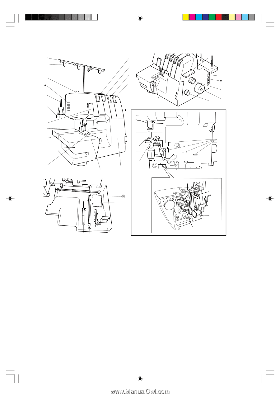
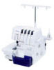
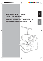
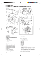
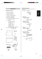
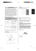
CHAPTER 1 NAMES OF PARTS AND THEIR FUNCTIONS 1 A F 2 B C 3 G D H 4 K I J 5 6 7 8 L O 9 0 E NM P Q 1 Thread tree 2 Thread plate 3 Presser foot pressure adjustment screw 4 Spool pin 5 Spool support 6 Thread take-up cover 7 Needles 8 Bed extension 9 Presser foot 0 Material plate cover A Left needle thread tension dial B Right needle thread tension dial C Upper looper thread tension dial D Lower looper thread tension dial E Front cover F Presser foot lifting lever G Main power and light switch H Stitch length adjustment dial 4 R S I Hand wheel J Differential feed ratio adjustment dial K Stitch width dial Inside of the front cover L Thread guide M Lower looper threading lever N Thread take up for loopers O Upper looper P Upper knife Q Lower looper R Stitch finger S Knife lever t Front cover compartment You can hold the included accessories and the removed stitch finger in this front cover compartment. : Needle set, : Stitch finger (when removed, see CHAPTER 5 "Narrow overlock/ Rolled hemming stitch"), : Tweezers, : Hexagonal driver * Air openings (on the side and back)
-
 1
1 -
 2
2 -
 3
3 -
 4
4 -
 5
5 -
 6
6 -
 7
7 -
 8
8 -
 9
9 -
 10
10 -
 11
11 -
 12
12 -
13
-
14
-
15
-
16
-
17
-
18
-
19
-
20
-
21
-
22
-
23
-
24
-
25
-
26
-
27
-
28
-
29
-
30
-
31
-
32
-
33
-
34
-
35
-
36
-
37
-
38
-
39
-
40
-
41
-
42
-
43
-
44
-
45
-
46
-
47
-
48
-
49
-
50
-
51
-
52
-
53
-
54
-
55
-
56
-
57
-
58
-
59
-
60
-
61
-
62
-
63
-
64
-
65
-
66
-
67
-
68
-
69
-
70
-
71
-
72
-
73
-
74
-
75
-
76
 |
 |