Canon 3200B002 User Manual - Page 20
Rear, Operation Panel, Air Vents, USB Connector, DIP Switches, Power Cord Connector, Menu Key
 |
View all Canon 3200B002 manuals
Add to My Manuals
Save this manual to your list of manuals |
Page 20 highlights
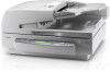
Rear Chapter 1 Before You Start Using the Scanner Operation Panel a Air Vents b USB Connector Connect a Hi-Speed USB 2.0 compatible USB cable here. (See p. 2-6.) c DIP Switches Configure these switches to specify the SCSI ID or terminator ON or OFF. (See p. 2-7.) d SCSI Connectors Connect a SCSI cable (50-pin half pitch, pin type) here. (See p. 2-7.) e Power Cord Connector Connect the provided power cord here. CAUTION • Never touch the cables at the rear of the scanner. Disconnection of these cables can cause a malfunction of the scanner. • Take care to ensure that the vents never become blocked. Blocked vents can lead to heat build-up inside of the scanner and create the risk of fire. a Menu Key Press this key to cycle the display through the various user modes, as shown below. (See "About the User Modes" on p. 4-2.) Co u n t On l y Mo d e ON [ OFF ] To t a l Coun t e r 0 L o n g Do c ume n t ON [ OFF ] S i ng l e - P as s Dup . [ ON ] OF F S t a n d - b y Mo d e 240 60 [ 10 ] USB Sh o r t Pa c k e t [ ON ] OF F Japanese ON [ OFF ] SCS I Sp e e d [ 20 ] 10 5 D i sp l ay Con t r as t b Set Keys Use these keys to change the setting of the currently displayed user mode. (See p. 4-3.) c Enter Key Press this key to register the currently displayed user mode setting. (See p. 4-3.) d Display Panel Displays the number of scanned pages, error codes, etc. 1-12
-
 1
1 -
2
-
3
-
4
-
5
-
6
-
7
-
8
-
9
-
10
-
11
-
12
-
13
-
14
-
 15
15 -
 16
16 -
 17
17 -
 18
18 -
 19
19 -
 20
20 -
 21
21 -
 22
22 -
 23
23 -
 24
24 -
 25
25 -
26
-
27
-
28
-
29
-
30
-
31
-
32
-
33
-
34
-
35
-
36
-
37
-
38
-
39
-
40
-
41
-
42
-
43
-
44
-
45
-
46
-
47
-
48
-
49
-
50
-
51
-
52
-
53
-
54
-
55
-
56
-
57
-
58
-
59
-
60
-
61
-
62
-
63
-
64
-
65
-
66
-
67
-
68
-
69
-
70
-
71
-
72
-
73
-
74
-
75
-
76
-
77
-
78
-
79
-
80
-
81
-
82
-
83
-
84
-
85
-
86
-
87
-
88
-
89
-
90
-
91
-
92
-
93
-
94
-
95
-
96
-
97
-
98
-
99
-
100
-
101
-
102
-
103
-
104
-
105
-
106
-
107
-
108
-
109
-
110
-
111
-
112
-
113
-
114
-
115
-
116
-
117
-
118
-
119
-
120
-
121
-
122
-
123
-
124
-
125
-
126
-
127
-
128
-
129
 |
 |
