Cisco AIR-LAP1131AG-E-K9 Hardware Installation Guide - Page 42
Mounting Access Point on a Network Cable Box, Mounting Access Point on a Desktop or Shelf, Attaching
 |
View all Cisco AIR-LAP1131AG-E-K9 manuals
Add to My Manuals
Save this manual to your list of manuals |
Page 42 highlights
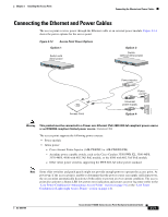
Mounting Access Point on a Network Cable Box Chapter 2 Installing the Access Point Step 8 Step 9 Step 10 Connect a drop wire to a building structural element and the hole provided in the bracket mounting clip. This additional support is required in order to comply with the U.S. National Electrical Safety Code. If you need additional security, you can secure the access point to a nearby immovable object using a Kensington lock and security cable (see the "Securing the Access Point" section on page 2-18). Verify that the access point is operating before replacing the ceiling tile. Mounting Access Point on a Network Cable Box Follow these steps to mount the access point on a network cable box. Step 1 Step 2 Step 3 Position the mounting plate over the network cable box and align the two mounting holes (labled with an X) with the network cable box holes. Hold the mounting plate and insert a 6 x 32 x 1/4 in. pan head screw into each of the two X mounting holes and tighten. Pull the access point cables out of the network box until there is about 1 foot of exposed cables protruding from the box. To attach the access point to the mounting plate, see the "Attaching the Access Point to the Mounting Plate" section on page 2-16. Mounting Access Point on a Desktop or Shelf When placing the access point on a desktop of shelf, you do not need the mounting plate. The access point has four rubber pads on the bottom to help prevent sliding or scratching the surface of your desktop or shelf. For information on connecting the access point cables, see the "Connecting the Ethernet and Power Cables" section on page 2-21. Attaching the Access Point to the Mounting Plate Follow these steps to attach the access point to the mounting plate: Step 1 Open the access point cover (see the "Opening the Access Point Cover" section on page 2-11). Step 2 In the cable bay area, pull the cables through the access point cable opening (see Figure 2-5). 2-16 Cisco Aironet 1130AG Series Access Point Hardware Installation Guide OL-8369-05
-
 1
1 -
2
-
3
-
4
-
5
-
6
-
7
-
8
-
9
-
10
-
11
-
12
-
13
-
14
-
15
-
16
-
17
-
18
-
19
-
20
-
21
-
22
-
23
-
24
-
25
-
26
-
27
-
28
-
29
-
30
-
31
-
32
-
33
-
34
-
35
-
36
-
 37
37 -
 38
38 -
 39
39 -
 40
40 -
 41
41 -
 42
42 -
 43
43 -
 44
44 -
 45
45 -
 46
46 -
 47
47 -
48
-
49
-
50
-
51
-
52
-
53
-
54
-
55
-
56
-
57
-
58
-
59
-
60
-
61
-
62
-
63
-
64
-
65
-
66
-
67
-
68
-
69
-
70
-
71
-
72
-
73
-
74
-
75
-
76
-
77
-
78
-
79
-
80
-
81
-
82
-
83
-
84
-
85
-
86
-
87
-
88
-
89
-
90
-
91
-
92
-
93
-
94
-
95
-
96
-
97
-
98
-
99
-
100
-
101
-
102
-
103
-
104
-
105
-
106
-
107
-
108
-
109
-
110
-
111
-
112
-
113
-
114
-
115
-
116
-
117
-
118
-
119
-
120
-
121
-
122
-
123
-
124
-
125
-
126
 |
 |
