Cisco AIR-LAP1131AG-E-K9 Hardware Installation Guide - Page 47
Connecting the Ethernet and Power Cables - air poe
 |
View all Cisco AIR-LAP1131AG-E-K9 manuals
Add to My Manuals
Save this manual to your list of manuals |
Page 47 highlights
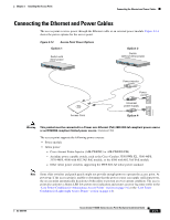
Chapter 2 Installing the Access Point Connecting the Ethernet and Power Cables Connecting the Ethernet and Power Cables The access point receives power through the Ethernet cable or an external power module. Figure 2-14 shows the power options for the access point. Figure 2-14 Access Point Power Options Option 1 Switch with inline power SYST RPS STAT UTIL DUPLX SPEED MODE 1 2 3 4 5 6 7 8 9 10 11 10Base-T / 100Base-TX 12 13 14 15 16 17 18 19 20 21 22 23 Catalyst 2950 SERIES 24 100Base-FX 23 24 Option 2 Switch (without inline power) SYST RPS STAT UTIL DUPLX SPEED MODE 1 2 3 4 5 6 7 8 9 10 11 10Base-T / 100Base-TX 12 13 14 15 16 17 18 19 20 21 22 23 Catalyst 2950 SERIES 24 100Base-FX 23 24 Access Point NETWOTROK Power injector AP/ BRITDOGE Power cord Universal power supply Option 4 121717 Warning This product must be connected to a Power over Ethernet (PoE) IEEE 802.3af compliant power source or an IEC60950 compliant limited power source. Statement 353 The access point supports the following power sources: • Power module • Inline power: - Cisco Aironet Power Injector (AIR-PWRINJ3 or AIR-PWRINJ-FIB) - An inline power capable switch, such as the Cisco Catalyst 3550 PWR XL, 3560-48PS, 3570-48PS, 4500 with 802.3AF PoE module, or the 6500 with 802.3AF PoE module - Other inline power switches supporting the IEEE 802.3af inline power standard Note Some older switches and patch panels might not provide enough power to operate the access point. At power-up, if the access point is unable to determine that the power source can supply sufficient power, the access point automatically deactivates both radios to prevent an over-current condition. The access point also activates a Status LED low power error indication and creates an error log entry (refer to the "Low Power Condition for Autonomous Access Points" section on page 3-6 or the "Low Power Condition for Lightweight Access Points" section on page 4-6). OL-8369-05 Cisco Aironet 1130AG Series Access Point Hardware Installation Guide 2-21
-
 1
1 -
2
-
3
-
4
-
5
-
6
-
7
-
8
-
9
-
10
-
11
-
12
-
13
-
14
-
15
-
16
-
17
-
18
-
19
-
20
-
21
-
22
-
23
-
24
-
25
-
26
-
27
-
28
-
29
-
30
-
31
-
32
-
33
-
34
-
35
-
36
-
37
-
38
-
39
-
40
-
41
-
 42
42 -
 43
43 -
 44
44 -
 45
45 -
 46
46 -
 47
47 -
 48
48 -
 49
49 -
 50
50 -
 51
51 -
 52
52 -
53
-
54
-
55
-
56
-
57
-
58
-
59
-
60
-
61
-
62
-
63
-
64
-
65
-
66
-
67
-
68
-
69
-
70
-
71
-
72
-
73
-
74
-
75
-
76
-
77
-
78
-
79
-
80
-
81
-
82
-
83
-
84
-
85
-
86
-
87
-
88
-
89
-
90
-
91
-
92
-
93
-
94
-
95
-
96
-
97
-
98
-
99
-
100
-
101
-
102
-
103
-
104
-
105
-
106
-
107
-
108
-
109
-
110
-
111
-
112
-
113
-
114
-
115
-
116
-
117
-
118
-
119
-
120
-
121
-
122
-
123
-
124
-
125
-
126
 |
 |
