Cisco AIR-LAP1131AG-E-K9 Hardware Installation Guide - Page 45
Securing the Access Point to the Mounting Plate
 |
View all Cisco AIR-LAP1131AG-E-K9 manuals
Add to My Manuals
Save this manual to your list of manuals |
Page 45 highlights
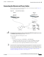
Chapter 2 Installing the Access Point Securing the Access Point Securing the Access Point to the Mounting Plate The mounting plate provides two methods of securing your access point to restrict its removal: • You can use the security hasp adapter (supplied) and a padlock (that you provide) to secure your access point to the mounting plate (refer to Figure 1-3 on page 1-7). Compatible padlocks are Master Lock models 120T or 121T. Note The security hasp adapter covers the cable bay area (including the power port, Ethernet port, console port, and the mode button) to prevent the installation or removal of the cables or the activation of the mode button. • You can use the 8 x 32 x 3/16 in. pan head screw (provided) or a tamper-resistant head screw (that you provide) to attach the access point to the mounting plate using the security screw hole (see Figure 2-10). Note Using a tamper-resistant head screw to secure the access point to the mounting plate does not prevent someone from inserting or removing the access point cables or pressing the mode button. Follow these instructions to install the security hasp adapter: Step 1 Step 2 Open the access point cover (see the "Opening the Access Point Cover" section on page 2-11). Carefully tilt the security hasp adapter and insert the access point security hasp tab into the notch on the security hasp adapter (see Figure 2-12). Figure 2-12 Installing the Security Hasp Adapter 121780 12 3 1 Access point security hasp tab 2 Security hasp notch 3 Security hasp adapter Step 3 Push down on the security hasp adapter to expose the padlock post hole. OL-8369-05 Cisco Aironet 1130AG Series Access Point Hardware Installation Guide 2-19
-
 1
1 -
2
-
3
-
4
-
5
-
6
-
7
-
8
-
9
-
10
-
11
-
12
-
13
-
14
-
15
-
16
-
17
-
18
-
19
-
20
-
21
-
22
-
23
-
24
-
25
-
26
-
27
-
28
-
29
-
30
-
31
-
32
-
33
-
34
-
35
-
36
-
37
-
38
-
39
-
 40
40 -
 41
41 -
 42
42 -
 43
43 -
 44
44 -
 45
45 -
 46
46 -
 47
47 -
 48
48 -
 49
49 -
 50
50 -
51
-
52
-
53
-
54
-
55
-
56
-
57
-
58
-
59
-
60
-
61
-
62
-
63
-
64
-
65
-
66
-
67
-
68
-
69
-
70
-
71
-
72
-
73
-
74
-
75
-
76
-
77
-
78
-
79
-
80
-
81
-
82
-
83
-
84
-
85
-
86
-
87
-
88
-
89
-
90
-
91
-
92
-
93
-
94
-
95
-
96
-
97
-
98
-
99
-
100
-
101
-
102
-
103
-
104
-
105
-
106
-
107
-
108
-
109
-
110
-
111
-
112
-
113
-
114
-
115
-
116
-
117
-
118
-
119
-
120
-
121
-
122
-
123
-
124
-
125
-
126
 |
 |
