Compaq Presario F700 HP G6000 Notebook PC and Compaq Presario F700 Notebook PC - Page 65
Lift the display assembly, straight up and remove it.
 |
View all Compaq Presario F700 manuals
Add to My Manuals
Save this manual to your list of manuals |
Page 65 highlights
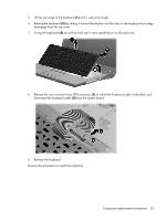
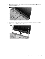
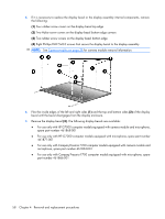
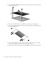
2. Remove the camera module cable and the wireless antenna cables from the clips (4) and routing channel built into the top cover. 3. Remove the four Phillips PM2.5×8.0 screws (1) that secure the display assembly to the computer. 4. Lift the display assembly (2) straight up and remove it. Component replacement procedures 57
-
 1
1 -
2
-
3
-
4
-
5
-
6
-
7
-
8
-
9
-
10
-
11
-
12
-
13
-
14
-
15
-
16
-
17
-
18
-
19
-
20
-
21
-
22
-
23
-
24
-
25
-
26
-
27
-
28
-
29
-
30
-
31
-
32
-
33
-
34
-
35
-
36
-
37
-
38
-
39
-
40
-
41
-
42
-
43
-
44
-
45
-
46
-
47
-
48
-
49
-
50
-
51
-
52
-
53
-
54
-
55
-
56
-
57
-
58
-
59
-
 60
60 -
 61
61 -
 62
62 -
 63
63 -
 64
64 -
 65
65 -
 66
66 -
 67
67 -
 68
68 -
 69
69 -
 70
70 -
71
-
72
-
73
-
74
-
75
-
76
-
77
-
78
-
79
-
80
-
81
-
82
-
83
-
84
-
85
-
86
-
87
-
88
-
89
-
90
-
91
-
92
-
93
-
94
-
95
-
96
-
97
-
98
-
99
-
100
-
101
-
102
-
103
-
104
-
105
-
106
-
107
-
108
-
109
-
110
-
111
-
112
-
113
-
114
-
115
-
116
-
117
-
118
-
119
-
120
-
121
-
122
-
123
-
124
-
125
-
126
-
127
-
128
-
129
-
130
-
131
-
132
-
133
 |
 |

2
.
Remove the camera module cable and the wireless antenna cables from the clips
(4)
and routing
channel built into the top cover.
3
.
Remove the four Phillips PM2.5×8.0 screws
(1)
that secure the display assembly to the computer.
4
.
Lift the display assembly
(2)
straight up and remove it.
Component replacement procedures
57