Compaq Presario F700 HP G6000 Notebook PC and Compaq Presario F700 Notebook PC - Page 79
Fan/heat sink assembly, Remove the fan/heat sink assembly
 |
View all Compaq Presario F700 manuals
Add to My Manuals
Save this manual to your list of manuals |
Page 79 highlights
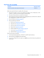
Fan/heat sink assembly Description Fan/heat sink assembly (includes replacement thermal material) Spare part number 449961-001 Before removing the fan/heat sink assembly, follow these steps: 1. Shut down the computer. If you are unsure whether the computer is off or in Hibernation, turn the computer on, and then shut it down through the operating system. 2. Disconnect all external devices connected to the computer. 3. Disconnect the power from the computer by first unplugging the power cord from the AC outlet and then unplugging the AC adapter from the computer. 4. Remove the battery (see Battery on page 37). 5. Remove the following components: a. Hard drive (see Hard drive on page 40) b. Optical drive (see Optical drive on page 48) c. Switch cover (see Switch cover on page 50) d. Keyboard (see Keyboard on page 52) e. Display assembly (see Display assembly on page 56) f. Top cover (see Top cover on page 63) g. System board (see System board on page 65) Remove the fan/heat sink assembly: 1. Turn the system board upside down, with the RJ-11 and RJ-45 jacks toward you. 2. Disconnect the fan cable (1) from the system board. 3. Loosen the four Phillips PM2.5×6.0 captive screws (2) that secure the fan/heat sink assembly to the system board. Component replacement procedures 71
-
 1
1 -
2
-
3
-
4
-
5
-
6
-
7
-
8
-
9
-
10
-
11
-
12
-
13
-
14
-
15
-
16
-
17
-
18
-
19
-
20
-
21
-
22
-
23
-
24
-
25
-
26
-
27
-
28
-
29
-
30
-
31
-
32
-
33
-
34
-
35
-
36
-
37
-
38
-
39
-
40
-
41
-
42
-
43
-
44
-
45
-
46
-
47
-
48
-
49
-
50
-
51
-
52
-
53
-
54
-
55
-
56
-
57
-
58
-
59
-
60
-
61
-
62
-
63
-
64
-
65
-
66
-
67
-
68
-
69
-
70
-
71
-
72
-
73
-
 74
74 -
 75
75 -
 76
76 -
 77
77 -
 78
78 -
 79
79 -
 80
80 -
 81
81 -
 82
82 -
 83
83 -
 84
84 -
85
-
86
-
87
-
88
-
89
-
90
-
91
-
92
-
93
-
94
-
95
-
96
-
97
-
98
-
99
-
100
-
101
-
102
-
103
-
104
-
105
-
106
-
107
-
108
-
109
-
110
-
111
-
112
-
113
-
114
-
115
-
116
-
117
-
118
-
119
-
120
-
121
-
122
-
123
-
124
-
125
-
126
-
127
-
128
-
129
-
130
-
131
-
132
-
133
 |
 |
