Craftsman 21221 Operation Manual
Craftsman 21221 - 12 in. Sliding Dual Bevel Compound Miter Saw Manual
 |
View all Craftsman 21221 manuals
Add to My Manuals
Save this manual to your list of manuals |
Craftsman 21221 manual content summary:
- Craftsman 21221 | Operation Manual - Page 1
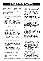
US CAUTION: Before using this Miter Saw, read this manual and follow all its Safety Rules and Operating Instructions • Safety Instructions • Installation • Operation • Maintenance • Parts List Customer Help Line For Technical Support 1-800-843-1682 Sears Parts & Repair Center 1-800-488-1222 - Craftsman 21221 | Operation Manual - Page 2
CRAFTSMAN ONE YEAR FULL WARRANTY If this Craftsman commercial or rental purposes. This warranty does not include expendable parts, such as lamps, batteries, bits or blades. This also have other rights which vary from state to state. Sears, Roebuck and Co., Hoffman Estates, IL 60179 _, WARNING - Craftsman 21221 | Operation Manual - Page 3
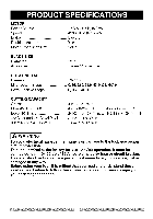
Insulated Yes Motor Arbor Shaft Size 5/8 in. BLADE SIZE Diameter Arbor size 12 in. 1 in.w/a 5/8 in.reducer ROTATING TABLE Diameter 13-7/16 in. Miter Detent Stops 0, 15, 22.5, 31.6, 45° R & L, 60 ° R Bevel Positive Stops 0, 33.9, 45 ° R & L CUTTING CAPACITY Crosscut 4 in. x 12-1/4 in - Craftsman 21221 | Operation Manual - Page 4
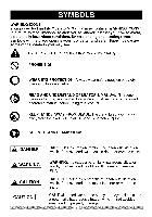
power tool and its Operator's Manual may contain "WARNING ICONS" (a picture symbol intended to alert you to, and/or instruct you how to avoid, manual before using this product. KEEP HANDS AWAY FROM BLADE: Failure to keep your hands away from the blade will result in serious personal injury. SUPPORT - Craftsman 21221 | Operation Manual - Page 5
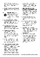
SAFETY INSTRUCTIONS BEFORE read and understood the following. . READ and become familiar with Manual. LEARN the tool's tahpepleicnatitrioen,Opleimraittoart'isons and possible hazards. , other jewelry which may get caught in moving parts. Nonslip footwear is recommended. Wear protective hair sears. 5 - Craftsman 21221 | Operation Manual - Page 6
break. and any other conditions that may affect its operation. A guard or other part that is damaged should be properly repaired or replaced. 13. WEAR A FACE MASK OR DUST MASK. Sawing operation produces dust. 14. SECURE WORK. Use cwlahmenpsproarctaicavli.seIttois hsoalfderwork than using your - Craftsman 21221 | Operation Manual - Page 7
SPECIFIC SAFETY INSTRUCTIONS FOR THIS COMPOUND MITER SAW . DO NOT operate the miter saw until it is completely assembled and installed according to these instructions. , IF YOU ARE NOT thoroughly familiar with the operation of miter saws, seek guidance from your supervisor, instructor or other - Craftsman 21221 | Operation Manual - Page 8
adequate support to the sides of the saw table for long work pieces. 23. NEVER use the miter saw in an area with flammable liquids or gases. 24. NEVER use solvents to clean plastic parts. Solvents could possibly dissolve or otherwise damage the material. 25. SHUT OFF the power before servicing or - Craftsman 21221 | Operation Manual - Page 9
Connect this saw to a 120 V circuit. Replacement parts - When servicing, use only identical replacement parts. This TROUBLESHOOTING To reduce the risk of electrical shock, this saw has a polarized plug (one blade is wider than the other). This plug will fit in a polarized outlet only one GUIDE - Craftsman 21221 | Operation Manual - Page 10
. For heavy loads, the voltage at motor terminals must equal the voltage specified on the nameplate. c. IMPROPER or dull saw blades are used. 5. Most motor troubles may be traced to loose or incorrect connections, overload, low voltage or inadequate power supply wiring. Always check the connections - Craftsman 21221 | Operation Manual - Page 11
miter saw. Follow instructions that accompany accessories. Use of improper accessories may cause hazards. • The use of any cutting tool except 12 in. saw to possible serious injury. ACCESSORIES Visit your Sears Hardware Department or see the Sears Power and Hand Tool Catalog to purchase recommended - Craftsman 21221 | Operation Manual - Page 12
Supplied Not supplied Blade Wrench Adjustable Wrench Phillips Screwdriver 6 mm Hex Wrench Slotted Screwdriver l !"'--''_,i i'-''-_, Combination Square COMBINATION SQUARE MUST BE TRUE Should not gap or overlap when square is flipped over (see dotted figure). Draw light line on board along - Craftsman 21221 | Operation Manual - Page 13
correctly replaced. To avoid electric shock, use only identical replacement parts when servicing double insulated tools. Call 1-800-4-MY-HOME ® for replacement parts. % Elbow Hold-down clamp Dust bag Miter saw Blade wrench Power cord storage clips 13 Power cord storage clip mounting hardware - Craftsman 21221 | Operation Manual - Page 14
ON/OFF trigger switch Lower blade guard Base Miter lock handle Left extension table Turntable Mounting hole Bevel lock handle Left support Hold-down latch Slide carriage Belt cover Quick-cam miter table lock Slide carriage lock knob Laser guide Right extension table Stop plate Table insert - Craftsman 21221 | Operation Manual - Page 15
. BASE - Supports the table, holds accessories and allows for workbench or leg set mounting. BEVEL LOCKING HANDLE - Locks the miter saw at a desired - Locks the miter saw in the lowered position for compact storage and transportation. INSTRUCTION OR OPERATOR'S MANUAL - Booklet accompanying your - Craftsman 21221 | Operation Manual - Page 16
miter is a type of joint where the two parts to be joined are cut at an angle, and typically the finished joint forms a 90-degree angle. Also commonly spelled "mitre". REVOLUTIONS PER MINUTE (RPM) - The number of turns completed by a spinning object in one minute. SAW a fence (guide), hold down or - Craftsman 21221 | Operation Manual - Page 17
ASSEMBLY TIME: 10~15 MINUTES AL WARNING I To avoid injury, do not connect this miter saw to the power source until it is completely assembled and adjusted, and you have read and understood this Operator's Manual, Unlocking 1. Push down slightly on the switch handle (1). 2. Pull out the hold-down - Craftsman 21221 | Operation Manual - Page 18
neck opening around the dust collection elbow (3), and release the metal collar. Fig. D THREE POSITION ROTATING HANDLE (FIG. E) The handle of the miter saw has been designed to rotate and lock at three different position stops; 450 left, 0 °, and 450 right for operator convenience. To rotate the - Craftsman 21221 | Operation Manual - Page 19
be removed for this purpose, but always reattach the table insert prior to performing a cutting operation. • Do not start the sliding compound miter saw without checking for interference between the blade and table insert. Damage could result to the blade, table insert or turntable if blade strike - Craftsman 21221 | Operation Manual - Page 20
clamp the saw to its support. Fig. I Mounting instructions 1. For stationary use, place the saw in the desired location, directly on a workbench where there is room for handling and proper support of the workpiece. The base of the saw has four mounting holes. Bolt the base of the miter saw (1) to - Craftsman 21221 | Operation Manual - Page 21
the OFF position and plug is not connected to the power source outlet. Only use a 12-inch diameter blade. 1. Unplug the saw from the outlet 2. Raise the miter saw to the upright position. 3. Raise the lower clear plastic blade guard (1) to the uppermost position. (Fig. L) . While holding the lower - Craftsman 21221 | Operation Manual - Page 22
blade. Also, the 12 in. blade has a 1 in. arbor hole with a 5/8 in. reducer (8) to mount onto the saw. Fig. N 8 \ 6 4 INSTALLING BLADE (FIG. L, M, N) WARNING J Un-plug the miter saw before changing/installing the blade. 1. Install a 12 in. blade with a 5/8 in. arbor (or a 1 in. arbor with a 5/8 in - Craftsman 21221 | Operation Manual - Page 23
instructions. saw blade path on the unqualified persons attempt stock to be cut before starting the miter to repair this laser product, saw. This laser guide service center personnel. to show. A. Check Laser Beam Alignment. WARNING I AVOID DIRECT EYE CONTACT • Laser radiated when laser guide - Craftsman 21221 | Operation Manual - Page 24
four set screws (1). Fig. 0 Laser Switch Fig. P THE UPFRONT SUPPORTS ADJUSTMENT (FIG. Q, R) Wide pieces need upfront supports (1). 1. Rotate the two upfront supports (1) toward the rear of the saw. Fig. Q i ...... l \ 1 NOTE: These supports (1) should be placed into the 0 position as shown in - Craftsman 21221 | Operation Manual - Page 25
the bevel detent pin (1) toward the front of the machine. NOTE: When retracting the bevel detent pin, it may be required to shift the miter saw upper arm assembly to the left/right. 2. Loosen the bevel lock handle (2) and tilt the cutting arm completely to the left. 3. Using a combination square - Craftsman 21221 | Operation Manual - Page 26
the bevel detent pin (1) toward the front of the machine. NOTE: When retracting the bevel detent pin, it may be required to shift the miter saw upper arm assembly to the left/right. 2. Loosen the bevel lock handle (2) and tilt the cutting arm completely to the right. 3. Using a combination square - Craftsman 21221 | Operation Manual - Page 27
here sitive ustment, rench NOTE: View from rear of machine MITER ANGLE ADJUSTMENT (FIG. X) The sliding compound miter saw scale can be easily read, showing miter angles from 0 ° to 45 ° to the left, and 0 ° to 45 ° to the right. The miter saw table has nine of the most common angle setttings with - Craftsman 21221 | Operation Manual - Page 28
shown to extend the locking arm against the base of the miter saw. 3. Test the quick cam miter lock to verify it locks the table into position SETTING CUTTING the table insert, and does not touch the control arm throat or any part of the base or table. If the maximum depth needs readjusting: 1. - Craftsman 21221 | Operation Manual - Page 29
BAR (FIG. BB) WARNING I To avoid possible personal injury or damage to the miter saw due to tipping, do not operate the saw without the Rear Extension Support Bar. Loosen the two screws (1) and extend the rear extension support bar (2) by sliding it out to match position, tighten the two screws. Fig - Craftsman 21221 | Operation Manual - Page 30
latch, bevel lock handle and cover plate screws. • Review and understand all safety instructions and operating procedures in this Operator's Manual. (SAFETY & OPERATIONS) • • Review the MAINTENANCE and TROUBLESHOOTING GUIDE for your miter saw. • To avoid injury or possible death from - Craftsman 21221 | Operation Manual - Page 31
Manual for recommended accessories. Follow the instructions that miter saw while any parts are moving. Avoid accidental starting, make sure the trigger switch is disengaged before plugging the miter saw ears. • Know your miter saw. Read and understand the Operator's Manual and labels affixed to the - Craftsman 21221 | Operation Manual - Page 32
part of the workpiece or as an additional support for a being cut. workpiece that is longer or wider Plan your work to avoid small pieces than the basic miter saw • Keep the cut off piece free to safety instructions, when cutting move sideways after it is cut off. non-ferrous metals: - Craftsman 21221 | Operation Manual - Page 33
does not stop within 10 seconds, unplug the saw and follow the instructions in TROUBLESHOOTING GUIDE section. Before freeing jammed material: • Release trigger switch. • Wait for all moving parts to stop. • Unplug the miter saw. Fig, CC i i i i i i i ® 8-3/4 in. o-Hand Zone i i ® 8-3/4 in. 33 - Craftsman 21221 | Operation Manual - Page 34
the hole (2) in the trigger switch, locking the tool's switch, preventing children and other unauthorized users from turning the machine on. The miter saw is equipped with an automatic blade brake. When the trigger switch is released, the electric blade brake will stop the blade within approximately - Craftsman 21221 | Operation Manual - Page 35
lever by pushing it out toward the rear of the machine. 2. Lift up on the sliding fence to remove it from the saw. Installing 1. Place the sliding fence onto the miter saw fence aligning the nut (1) with the slot (4). 2. To lock the sliding fence, push the cam-locking lever in toward the front - Craftsman 21221 | Operation Manual - Page 36
will not allow enough space for the blade to pass through which could result in serious injury. At extreme miter or bevel angles the saw blade may also contact the fence. NOTE: The saw comes with a 33.9 ° bevel detent pin for setting up crown molding cuts when the angle of the walls equals - Craftsman 21221 | Operation Manual - Page 37
angle and lock the quick cam miter table lock (3). 4. Position the workpiece on the table and against the fence. Use a hold down clamp (4) attached to the base, whenever possible. 5. Pull the trigger (5), turning on the saw. Lower the blade by pushing the handle (6) down into the workpiece with - Craftsman 21221 | Operation Manual - Page 38
or REMOVE SLIDING FENCE", 3. Set both the desired bevel angle and/or the miter angle and lock into position. 4. If bevel cutting, set both the left and BOARDS (FIG, MM) 1. Rotate the two upfront supports (7) toward the rear of the saw. 2. Unlock the carriage lock knob (1) and allow the cutting head - Craftsman 21221 | Operation Manual - Page 39
the stop plate (1). 4. Cut two parallel grooves as shown below. Fig. OO Fig. NN Cut these grooves with saw Use a chisel to cut out the middle TELESCOPING WORKPIECE SUPPORT & REPETITIVE CUTTING USING THE STOP PLATE (FIG. PP) Long pieces need extension table ROUGH CUTTING A DADO (FIG. OO - Craftsman 21221 | Operation Manual - Page 40
the blade guard and housing, possibly causing damage or injury. To minimize this an auxiliary wood fence can be mounted to your saw. Holes are provided in the saw fence to attach an auxiliary wood fence (this provides additional depth of cut). This fence should be constructed of straight auxiliary - Craftsman 21221 | Operation Manual - Page 41
the settings are interdependent; changing one changes the other, as well. Fig. UU Fig. TT ne Miter saw table miter at 450, bevel at 0° _table miter at 0°, bevel at 450 Miter saw table Bevel/Miter Settings Fig. VV NOTE: Always perform a dry run cut so you can determine if the operation being - Craftsman 21221 | Operation Manual - Page 42
set at RIGHT 31.6 ° . 3. LEFT side is finished piece. Inside corner-Right side IR 33.9 ° 31.6 ° Left 1. Position bottom of molding against fence. 2. Miter table set at LEFT 31.6 °. OL 33.9 ° OR 33.9 ° 31.6 ° Left 31.6 o Right 3. LEFT side is finished piece. Outside corner-Left 1. Position - Craftsman 21221 | Operation Manual - Page 43
CROWN MOLDING CHART Compound Miter saw Miter and bevel Angle settings Wall to Crown Molding Angle Angle Between Walls 67 68 5.12 4.72 4.33 3.94 3.84 3.18 2.75 2.36 1.97 1.58 1.18 0.79 0.39 45/45 ° Crown Molding Miter Setting 20.61 20.21 19.81 19.42 19.03 18.64 18.25 17.86 17.48 17.09 16.71 16.32 - Craftsman 21221 | Operation Manual - Page 44
, naphtha acetone, lacquer thinner or similar highly volatile solvents to clean the miter saw. _IL WARNING I To avoid injury from unexpected starting or electrical shock, unplug the power cord before working on the saw. the carbon part fits into. Tighten the cap snugly, but do not overtighten. NOTE - Craftsman 21221 | Operation Manual - Page 45
Periodically, sawdust will accumulate under the work table and base. This could cause difficulty in the movement of the worktable when setting up a miter cut. Frequently blow out or vacuum up the sawdust. WARNING J If blowing sawdust, wear proper eye protection to keep debris from entering eyes - Craftsman 21221 | Operation Manual - Page 46
moving, replacing the blade or making adjustments, TROUBLESHOOTING GUIDE - MOTOR PROBLEM PROBLEM CAUSE Brake does , Motor brushes not sealed REMOVING OR INSTALLING THE BLADE section. 4. Replace brushes. 5. Contact Sears Service Center. 1. Replace limit switch. 2. Replace brushes. See MAINTENANCE - Craftsman 21221 | Operation Manual - Page 47
TROUBLESHOOTING GUIDE - SAW OPERATION PROBLEM PROBLEM CAUSE Blade hits table. Angle of cut not accurate. Can not adjust miter. Cutting arm wobbles. Cutting arm will not fully raise, or blade guard won't fully close. Blade binds, ams, burns wood. 1. Misalignment. 1. Miter table unlocked. 2. - Craftsman 21221 | Operation Manual - Page 48
CRAFTSMAN replacement parts. Use of any other parts many create a HAZARD or cause product damage. Any attempt to repair or replace electrical parts on this Miter Saw may create a HAZARD unless repair is done by a qualified service technician. Repair service is available at your nearest Sears Service - Craftsman 21221 | Operation Manual - Page 49
262U 145V 2QU3 246_ 0 I1"1 I" Z 0 2LK2 2CG'['4_i ".4 OI,MH k) 2P4_ 43B z o - Craftsman 21221 | Operation Manual - Page 50
MITER SAW MODEL NO. 137.212210 PARTS LIST FOR SAW SCHEMATIC B I.D. Description Size 0831 SHAFT SLEEVE 2750 2841 CAUTION LABEL CENTER SHAFT OCEZ PLUNGER HANDLE OD7Z KNOB-HANDLE ODW5 POWER CORD CLAMP OH9W CLEVIS PiN OHAM DUST SHIELD OHAN PLATE COVER OHAP SLIDE-BAR GUIDE SUPPORT(LEFT) SUPPORT - Craftsman 21221 | Operation Manual - Page 51
26HX / 26PU /27BC 2SY9 \ \ \ _?HE ", , 083I__ OH9W 27J9 \OJBO 262V 26P7 25YK / 0Jppz / ./ 0KMYa OJXO / 26NS ENGV 25YG / Z .N" Ill • 0 w0 C Z o -I r,n r_ 0 o I'll rZ 0 0) o - Craftsman 21221 | Operation Manual - Page 52
12 in. COMPOUND MITER SAW PARTS LIST FOR SAW SCHEMATIC C MODEL NO. 137.212210 I.D. Description 2258 SPECIAL BOLT Size Qty I.D. Description I 25V3 KNOB Size Qty 4 2754 WARNING LABEL I 25XX BASE #AW I 082J CUSHION 2 25Y0 - Craftsman 21221 | Operation Manual - Page 53
27KP +_/+'+L+ io+_ I J J \ \25XX J J \%// Z .N" m• _0 0 "u o0 C Z 0 -I r,n r_ 0 0 I'll r- Z /+ 0 0) o - Craftsman 21221 | Operation Manual - Page 54
12 in. COMPOUND MITER SAW PARTS LIST FOR MOTOR I.D. OJB8 OJX3 OJXC 0K38 OK3T SCREW & WASHER CR. RE. PAN HD. SCREW & WASHER CR. RE. PAN HD. SCREW & WASHER PLASTIC SCREW FLOW GUIDE BRUSH HOLDER ASS'Y BRUSH ASS'Y BRUSH COVER RUBBER PIN ARMATURE ASS'Y FRONT HOUSING MOTOR PULLEY FIELD ASS'Y CR. RE. PAN - Craftsman 21221 | Operation Manual - Page 55
55 - Craftsman 21221 | Operation Manual - Page 56
the replacement parts, accessories and owner's manuals that you need to do-it-yourself. For Sears professional Sears Parts & Repair Service Center 1-800-488-1222 (U.S.A.) www.sears.com 1-800-469-4663 (Canada) www.sears.ca To purchase a protection agreement on a product serviced by Sears - Craftsman 21221 | Operation Manual - Page 57
US CAUTION: Before using this Miter Saw, read this manual and follow all its Safety Rules and Operating Instructions • Safety Instructions • Installation • Operation • Maintenance • Parts List Customer Help Line For Technical Support 1-800-843-1682 Sears Parts & Repair Center 1-800-488-1222 - Craftsman 21221 | Operation Manual - Page 58
CRAFTSMAN ONE YEAR FULL WARRANTY If this Craftsman commercial or rental purposes. This warranty does not include expendable parts, such as lamps, batteries, bits or blades. This also have other rights which vary from state to state. Sears, Roebuck and Co., Hoffman Estates, IL 60179 _, WARNING - Craftsman 21221 | Operation Manual - Page 59
Insulated Yes Motor Arbor Shaft Size 5/8 in. BLADE SIZE Diameter Arbor size 12 in. 1 in.w/a 5/8 in.reducer ROTATING TABLE Diameter 13-7/16 in. Miter Detent Stops 0, 15, 22.5, 31.6, 45° R & L, 60 ° R Bevel Positive Stops 0, 33.9, 45 ° R & L CUTTING CAPACITY Crosscut 4 in. x 12-1/4 in - Craftsman 21221 | Operation Manual - Page 60
power tool and its Operator's Manual may contain "WARNING ICONS" (a picture symbol intended to alert you to, and/or instruct you how to avoid, manual before using this product. KEEP HANDS AWAY FROM BLADE: Failure to keep your hands away from the blade will result in serious personal injury. SUPPORT - Craftsman 21221 | Operation Manual - Page 61
SAFETY INSTRUCTIONS BEFORE read and understood the following. . READ and become familiar with Manual. LEARN the tool's tahpepleicnatitrioen,Opleimraittoart'isons and possible hazards. , other jewelry which may get caught in moving parts. Nonslip footwear is recommended. Wear protective hair sears. 5 - Craftsman 21221 | Operation Manual - Page 62
break. and any other conditions that may affect its operation. A guard or other part that is damaged should be properly repaired or replaced. 13. WEAR A FACE MASK OR DUST MASK. Sawing operation produces dust. 14. SECURE WORK. Use cwlahmenpsproarctaicavli.seIttois hsoalfderwork than using your - Craftsman 21221 | Operation Manual - Page 63
SPECIFIC SAFETY INSTRUCTIONS FOR THIS COMPOUND MITER SAW . DO NOT operate the miter saw until it is completely assembled and installed according to these instructions. , IF YOU ARE NOT thoroughly familiar with the operation of miter saws, seek guidance from your supervisor, instructor or other - Craftsman 21221 | Operation Manual - Page 64
adequate support to the sides of the saw table for long work pieces. 23. NEVER use the miter saw in an area with flammable liquids or gases. 24. NEVER use solvents to clean plastic parts. Solvents could possibly dissolve or otherwise damage the material. 25. SHUT OFF the power before servicing or - Craftsman 21221 | Operation Manual - Page 65
Connect this saw to a 120 V circuit. Replacement parts - When servicing, use only identical replacement parts. This TROUBLESHOOTING To reduce the risk of electrical shock, this saw has a polarized plug (one blade is wider than the other). This plug will fit in a polarized outlet only one GUIDE - Craftsman 21221 | Operation Manual - Page 66
. For heavy loads, the voltage at motor terminals must equal the voltage specified on the nameplate. c. IMPROPER or dull saw blades are used. 5. Most motor troubles may be traced to loose or incorrect connections, overload, low voltage or inadequate power supply wiring. Always check the connections - Craftsman 21221 | Operation Manual - Page 67
miter saw. Follow instructions that accompany accessories. Use of improper accessories may cause hazards. • The use of any cutting tool except 12 in. saw to possible serious injury. ACCESSORIES Visit your Sears Hardware Department or see the Sears Power and Hand Tool Catalog to purchase recommended - Craftsman 21221 | Operation Manual - Page 68
Supplied Not supplied Blade Wrench Adjustable Wrench Phillips Screwdriver 6 mm Hex Wrench Slotted Screwdriver l !"'--''_,i i'-''-_, Combination Square COMBINATION SQUARE MUST BE TRUE Should not gap or overlap when square is flipped over (see dotted figure). Draw light line on board along - Craftsman 21221 | Operation Manual - Page 69
correctly replaced. To avoid electric shock, use only identical replacement parts when servicing double insulated tools. Call 1-800-4-MY-HOME ® for replacement parts. % Elbow Hold-down clamp Dust bag Miter saw Blade wrench Power cord storage clips 13 Power cord storage clip mounting hardware - Craftsman 21221 | Operation Manual - Page 70
ON/OFF trigger switch Lower blade guard Base Miter lock handle Left extension table Turntable Mounting hole Bevel lock handle Left support Hold-down latch Slide carriage Belt cover Quick-cam miter table lock Slide carriage lock knob Laser guide Right extension table Stop plate Table insert - Craftsman 21221 | Operation Manual - Page 71
. BASE - Supports the table, holds accessories and allows for workbench or leg set mounting. BEVEL LOCKING HANDLE - Locks the miter saw at a desired - Locks the miter saw in the lowered position for compact storage and transportation. INSTRUCTION OR OPERATOR'S MANUAL - Booklet accompanying your - Craftsman 21221 | Operation Manual - Page 72
miter is a type of joint where the two parts to be joined are cut at an angle, and typically the finished joint forms a 90-degree angle. Also commonly spelled "mitre". REVOLUTIONS PER MINUTE (RPM) - The number of turns completed by a spinning object in one minute. SAW a fence (guide), hold down or - Craftsman 21221 | Operation Manual - Page 73
ASSEMBLY TIME: 10~15 MINUTES AL WARNING I To avoid injury, do not connect this miter saw to the power source until it is completely assembled and adjusted, and you have read and understood this Operator's Manual, Unlocking 1. Push down slightly on the switch handle (1). 2. Pull out the hold-down - Craftsman 21221 | Operation Manual - Page 74
neck opening around the dust collection elbow (3), and release the metal collar. Fig. D THREE POSITION ROTATING HANDLE (FIG. E) The handle of the miter saw has been designed to rotate and lock at three different position stops; 450 left, 0 °, and 450 right for operator convenience. To rotate the - Craftsman 21221 | Operation Manual - Page 75
be removed for this purpose, but always reattach the table insert prior to performing a cutting operation. • Do not start the sliding compound miter saw without checking for interference between the blade and table insert. Damage could result to the blade, table insert or turntable if blade strike - Craftsman 21221 | Operation Manual - Page 76
clamp the saw to its support. Fig. I Mounting instructions 1. For stationary use, place the saw in the desired location, directly on a workbench where there is room for handling and proper support of the workpiece. The base of the saw has four mounting holes. Bolt the base of the miter saw (1) to - Craftsman 21221 | Operation Manual - Page 77
the OFF position and plug is not connected to the power source outlet. Only use a 12-inch diameter blade. 1. Unplug the saw from the outlet 2. Raise the miter saw to the upright position. 3. Raise the lower clear plastic blade guard (1) to the uppermost position. (Fig. L) . While holding the lower - Craftsman 21221 | Operation Manual - Page 78
blade. Also, the 12 in. blade has a 1 in. arbor hole with a 5/8 in. reducer (8) to mount onto the saw. Fig. N 8 \ 6 4 INSTALLING BLADE (FIG. L, M, N) WARNING J Un-plug the miter saw before changing/installing the blade. 1. Install a 12 in. blade with a 5/8 in. arbor (or a 1 in. arbor with a 5/8 in - Craftsman 21221 | Operation Manual - Page 79
instructions. saw blade path on the unqualified persons attempt stock to be cut before starting the miter to repair this laser product, saw. This laser guide service center personnel. to show. A. Check Laser Beam Alignment. WARNING I AVOID DIRECT EYE CONTACT • Laser radiated when laser guide - Craftsman 21221 | Operation Manual - Page 80
four set screws (1). Fig. 0 Laser Switch Fig. P THE UPFRONT SUPPORTS ADJUSTMENT (FIG. Q, R) Wide pieces need upfront supports (1). 1. Rotate the two upfront supports (1) toward the rear of the saw. Fig. Q i ...... l \ 1 NOTE: These supports (1) should be placed into the 0 position as shown in - Craftsman 21221 | Operation Manual - Page 81
the bevel detent pin (1) toward the front of the machine. NOTE: When retracting the bevel detent pin, it may be required to shift the miter saw upper arm assembly to the left/right. 2. Loosen the bevel lock handle (2) and tilt the cutting arm completely to the left. 3. Using a combination square - Craftsman 21221 | Operation Manual - Page 82
the bevel detent pin (1) toward the front of the machine. NOTE: When retracting the bevel detent pin, it may be required to shift the miter saw upper arm assembly to the left/right. 2. Loosen the bevel lock handle (2) and tilt the cutting arm completely to the right. 3. Using a combination square - Craftsman 21221 | Operation Manual - Page 83
here sitive ustment, rench NOTE: View from rear of machine MITER ANGLE ADJUSTMENT (FIG. X) The sliding compound miter saw scale can be easily read, showing miter angles from 0 ° to 45 ° to the left, and 0 ° to 45 ° to the right. The miter saw table has nine of the most common angle setttings with - Craftsman 21221 | Operation Manual - Page 84
shown to extend the locking arm against the base of the miter saw. 3. Test the quick cam miter lock to verify it locks the table into position SETTING CUTTING the table insert, and does not touch the control arm throat or any part of the base or table. If the maximum depth needs readjusting: 1. - Craftsman 21221 | Operation Manual - Page 85
BAR (FIG. BB) WARNING I To avoid possible personal injury or damage to the miter saw due to tipping, do not operate the saw without the Rear Extension Support Bar. Loosen the two screws (1) and extend the rear extension support bar (2) by sliding it out to match position, tighten the two screws. Fig - Craftsman 21221 | Operation Manual - Page 86
latch, bevel lock handle and cover plate screws. • Review and understand all safety instructions and operating procedures in this Operator's Manual. (SAFETY & OPERATIONS) • • Review the MAINTENANCE and TROUBLESHOOTING GUIDE for your miter saw. • To avoid injury or possible death from - Craftsman 21221 | Operation Manual - Page 87
Manual for recommended accessories. Follow the instructions that miter saw while any parts are moving. Avoid accidental starting, make sure the trigger switch is disengaged before plugging the miter saw ears. • Know your miter saw. Read and understand the Operator's Manual and labels affixed to the - Craftsman 21221 | Operation Manual - Page 88
part of the workpiece or as an additional support for a being cut. workpiece that is longer or wider Plan your work to avoid small pieces than the basic miter saw • Keep the cut off piece free to safety instructions, when cutting move sideways after it is cut off. non-ferrous metals: - Craftsman 21221 | Operation Manual - Page 89
does not stop within 10 seconds, unplug the saw and follow the instructions in TROUBLESHOOTING GUIDE section. Before freeing jammed material: • Release trigger switch. • Wait for all moving parts to stop. • Unplug the miter saw. Fig, CC i i i i i i i ® 8-3/4 in. o-Hand Zone i i ® 8-3/4 in. 33 - Craftsman 21221 | Operation Manual - Page 90
the hole (2) in the trigger switch, locking the tool's switch, preventing children and other unauthorized users from turning the machine on. The miter saw is equipped with an automatic blade brake. When the trigger switch is released, the electric blade brake will stop the blade within approximately - Craftsman 21221 | Operation Manual - Page 91
lever by pushing it out toward the rear of the machine. 2. Lift up on the sliding fence to remove it from the saw. Installing 1. Place the sliding fence onto the miter saw fence aligning the nut (1) with the slot (4). 2. To lock the sliding fence, push the cam-locking lever in toward the front - Craftsman 21221 | Operation Manual - Page 92
will not allow enough space for the blade to pass through which could result in serious injury. At extreme miter or bevel angles the saw blade may also contact the fence. NOTE: The saw comes with a 33.9 ° bevel detent pin for setting up crown molding cuts when the angle of the walls equals - Craftsman 21221 | Operation Manual - Page 93
angle and lock the quick cam miter table lock (3). 4. Position the workpiece on the table and against the fence. Use a hold down clamp (4) attached to the base, whenever possible. 5. Pull the trigger (5), turning on the saw. Lower the blade by pushing the handle (6) down into the workpiece with - Craftsman 21221 | Operation Manual - Page 94
or REMOVE SLIDING FENCE", 3. Set both the desired bevel angle and/or the miter angle and lock into position. 4. If bevel cutting, set both the left and BOARDS (FIG, MM) 1. Rotate the two upfront supports (7) toward the rear of the saw. 2. Unlock the carriage lock knob (1) and allow the cutting head - Craftsman 21221 | Operation Manual - Page 95
the stop plate (1). 4. Cut two parallel grooves as shown below. Fig. OO Fig. NN Cut these grooves with saw Use a chisel to cut out the middle TELESCOPING WORKPIECE SUPPORT & REPETITIVE CUTTING USING THE STOP PLATE (FIG. PP) Long pieces need extension table ROUGH CUTTING A DADO (FIG. OO - Craftsman 21221 | Operation Manual - Page 96
the blade guard and housing, possibly causing damage or injury. To minimize this an auxiliary wood fence can be mounted to your saw. Holes are provided in the saw fence to attach an auxiliary wood fence (this provides additional depth of cut). This fence should be constructed of straight auxiliary - Craftsman 21221 | Operation Manual - Page 97
the settings are interdependent; changing one changes the other, as well. Fig. UU Fig. TT ne Miter saw table miter at 450, bevel at 0° _table miter at 0°, bevel at 450 Miter saw table Bevel/Miter Settings Fig. VV NOTE: Always perform a dry run cut so you can determine if the operation being - Craftsman 21221 | Operation Manual - Page 98
set at RIGHT 31.6 ° . 3. LEFT side is finished piece. Inside corner-Right side IR 33.9 ° 31.6 ° Left 1. Position bottom of molding against fence. 2. Miter table set at LEFT 31.6 °. OL 33.9 ° OR 33.9 ° 31.6 ° Left 31.6 o Right 3. LEFT side is finished piece. Outside corner-Left 1. Position - Craftsman 21221 | Operation Manual - Page 99
CROWN MOLDING CHART Compound Miter saw Miter and bevel Angle settings Wall to Crown Molding Angle Angle Between Walls 67 68 5.12 4.72 4.33 3.94 3.84 3.18 2.75 2.36 1.97 1.58 1.18 0.79 0.39 45/45 ° Crown Molding Miter Setting 20.61 20.21 19.81 19.42 19.03 18.64 18.25 17.86 17.48 17.09 16.71 16.32 - Craftsman 21221 | Operation Manual - Page 100
, naphtha acetone, lacquer thinner or similar highly volatile solvents to clean the miter saw. _IL WARNING I To avoid injury from unexpected starting or electrical shock, unplug the power cord before working on the saw. the carbon part fits into. Tighten the cap snugly, but do not overtighten. NOTE - Craftsman 21221 | Operation Manual - Page 101
Periodically, sawdust will accumulate under the work table and base. This could cause difficulty in the movement of the worktable when setting up a miter cut. Frequently blow out or vacuum up the sawdust. WARNING J If blowing sawdust, wear proper eye protection to keep debris from entering eyes - Craftsman 21221 | Operation Manual - Page 102
moving, replacing the blade or making adjustments, TROUBLESHOOTING GUIDE - MOTOR PROBLEM PROBLEM CAUSE Brake does , Motor brushes not sealed REMOVING OR INSTALLING THE BLADE section. 4. Replace brushes. 5. Contact Sears Service Center. 1. Replace limit switch. 2. Replace brushes. See MAINTENANCE - Craftsman 21221 | Operation Manual - Page 103
TROUBLESHOOTING GUIDE - SAW OPERATION PROBLEM PROBLEM CAUSE Blade hits table. Angle of cut not accurate. Can not adjust miter. Cutting arm wobbles. Cutting arm will not fully raise, or blade guard won't fully close. Blade binds, ams, burns wood. 1. Misalignment. 1. Miter table unlocked. 2. - Craftsman 21221 | Operation Manual - Page 104
CRAFTSMAN replacement parts. Use of any other parts many create a HAZARD or cause product damage. Any attempt to repair or replace electrical parts on this Miter Saw may create a HAZARD unless repair is done by a qualified service technician. Repair service is available at your nearest Sears Service - Craftsman 21221 | Operation Manual - Page 105
262U 145V 2QU3 246_ 0 I1"1 I" Z 0 2LK2 2CG'['4_i ".4 OI,MH k) 2P4_ 43B z o - Craftsman 21221 | Operation Manual - Page 106
MITER SAW MODEL NO. 137.212210 PARTS LIST FOR SAW SCHEMATIC B I.D. Description Size 0831 SHAFT SLEEVE 2750 2841 CAUTION LABEL CENTER SHAFT OCEZ PLUNGER HANDLE OD7Z KNOB-HANDLE ODW5 POWER CORD CLAMP OH9W CLEVIS PiN OHAM DUST SHIELD OHAN PLATE COVER OHAP SLIDE-BAR GUIDE SUPPORT(LEFT) SUPPORT - Craftsman 21221 | Operation Manual - Page 107
26HX / 26PU /27BC 2SY9 \ \ \ _?HE ", , 083I__ OH9W 27J9 \OJBO 262V 26P7 25YK / 0Jppz / ./ 0KMYa OJXO / 26NS ENGV 25YG / Z .N" Ill • 0 w0 C Z o -I r,n r_ 0 o I'll rZ 0 0) o - Craftsman 21221 | Operation Manual - Page 108
12 in. COMPOUND MITER SAW PARTS LIST FOR SAW SCHEMATIC C MODEL NO. 137.212210 I.D. Description 2258 SPECIAL BOLT Size Qty I.D. Description I 25V3 KNOB Size Qty 4 2754 WARNING LABEL I 25XX BASE #AW I 082J CUSHION 2 25Y0 - Craftsman 21221 | Operation Manual - Page 109
27KP +_/+'+L+ io+_ I J J \ \25XX J J \%// Z .N" m• _0 0 "u o0 C Z 0 -I r,n r_ 0 0 I'll r- Z /+ 0 0) o - Craftsman 21221 | Operation Manual - Page 110
12 in. COMPOUND MITER SAW PARTS LIST FOR MOTOR I.D. OJB8 OJX3 OJXC 0K38 OK3T SCREW & WASHER CR. RE. PAN HD. SCREW & WASHER CR. RE. PAN HD. SCREW & WASHER PLASTIC SCREW FLOW GUIDE BRUSH HOLDER ASS'Y BRUSH ASS'Y BRUSH COVER RUBBER PIN ARMATURE ASS'Y FRONT HOUSING MOTOR PULLEY FIELD ASS'Y CR. RE. PAN - Craftsman 21221 | Operation Manual - Page 111
55 - Craftsman 21221 | Operation Manual - Page 112
the replacement parts, accessories and owner's manuals that you need to do-it-yourself. For Sears professional Sears Parts & Repair Service Center 1-800-488-1222 (U.S.A.) www.sears.com 1-800-469-4663 (Canada) www.sears.ca To purchase a protection agreement on a product serviced by Sears - Craftsman 21221 | Operation Manual - Page 113
US CAUTION: Before using this Miter Saw, read this manual and follow all its Safety Rules and Operating Instructions • Safety Instructions • Installation • Operation • Maintenance • Parts List Customer Help Line For Technical Support 1-800-843-1682 Sears Parts & Repair Center 1-800-488-1222 - Craftsman 21221 | Operation Manual - Page 114
CRAFTSMAN ONE YEAR FULL WARRANTY If this Craftsman commercial or rental purposes. This warranty does not include expendable parts, such as lamps, batteries, bits or blades. This also have other rights which vary from state to state. Sears, Roebuck and Co., Hoffman Estates, IL 60179 _, WARNING - Craftsman 21221 | Operation Manual - Page 115
Insulated Yes Motor Arbor Shaft Size 5/8 in. BLADE SIZE Diameter Arbor size 12 in. 1 in.w/a 5/8 in.reducer ROTATING TABLE Diameter 13-7/16 in. Miter Detent Stops 0, 15, 22.5, 31.6, 45° R & L, 60 ° R Bevel Positive Stops 0, 33.9, 45 ° R & L CUTTING CAPACITY Crosscut 4 in. x 12-1/4 in - Craftsman 21221 | Operation Manual - Page 116
power tool and its Operator's Manual may contain "WARNING ICONS" (a picture symbol intended to alert you to, and/or instruct you how to avoid, manual before using this product. KEEP HANDS AWAY FROM BLADE: Failure to keep your hands away from the blade will result in serious personal injury. SUPPORT - Craftsman 21221 | Operation Manual - Page 117
SAFETY INSTRUCTIONS BEFORE read and understood the following. . READ and become familiar with Manual. LEARN the tool's tahpepleicnatitrioen,Opleimraittoart'isons and possible hazards. , other jewelry which may get caught in moving parts. Nonslip footwear is recommended. Wear protective hair sears. 5 - Craftsman 21221 | Operation Manual - Page 118
break. and any other conditions that may affect its operation. A guard or other part that is damaged should be properly repaired or replaced. 13. WEAR A FACE MASK OR DUST MASK. Sawing operation produces dust. 14. SECURE WORK. Use cwlahmenpsproarctaicavli.seIttois hsoalfderwork than using your - Craftsman 21221 | Operation Manual - Page 119
SPECIFIC SAFETY INSTRUCTIONS FOR THIS COMPOUND MITER SAW . DO NOT operate the miter saw until it is completely assembled and installed according to these instructions. , IF YOU ARE NOT thoroughly familiar with the operation of miter saws, seek guidance from your supervisor, instructor or other - Craftsman 21221 | Operation Manual - Page 120
adequate support to the sides of the saw table for long work pieces. 23. NEVER use the miter saw in an area with flammable liquids or gases. 24. NEVER use solvents to clean plastic parts. Solvents could possibly dissolve or otherwise damage the material. 25. SHUT OFF the power before servicing or - Craftsman 21221 | Operation Manual - Page 121
Connect this saw to a 120 V circuit. Replacement parts - When servicing, use only identical replacement parts. This TROUBLESHOOTING To reduce the risk of electrical shock, this saw has a polarized plug (one blade is wider than the other). This plug will fit in a polarized outlet only one GUIDE - Craftsman 21221 | Operation Manual - Page 122
. For heavy loads, the voltage at motor terminals must equal the voltage specified on the nameplate. c. IMPROPER or dull saw blades are used. 5. Most motor troubles may be traced to loose or incorrect connections, overload, low voltage or inadequate power supply wiring. Always check the connections - Craftsman 21221 | Operation Manual - Page 123
miter saw. Follow instructions that accompany accessories. Use of improper accessories may cause hazards. • The use of any cutting tool except 12 in. saw to possible serious injury. ACCESSORIES Visit your Sears Hardware Department or see the Sears Power and Hand Tool Catalog to purchase recommended - Craftsman 21221 | Operation Manual - Page 124
Supplied Not supplied Blade Wrench Adjustable Wrench Phillips Screwdriver 6 mm Hex Wrench Slotted Screwdriver l !"'--''_,i i'-''-_, Combination Square COMBINATION SQUARE MUST BE TRUE Should not gap or overlap when square is flipped over (see dotted figure). Draw light line on board along - Craftsman 21221 | Operation Manual - Page 125
correctly replaced. To avoid electric shock, use only identical replacement parts when servicing double insulated tools. Call 1-800-4-MY-HOME ® for replacement parts. % Elbow Hold-down clamp Dust bag Miter saw Blade wrench Power cord storage clips 13 Power cord storage clip mounting hardware - Craftsman 21221 | Operation Manual - Page 126
ON/OFF trigger switch Lower blade guard Base Miter lock handle Left extension table Turntable Mounting hole Bevel lock handle Left support Hold-down latch Slide carriage Belt cover Quick-cam miter table lock Slide carriage lock knob Laser guide Right extension table Stop plate Table insert - Craftsman 21221 | Operation Manual - Page 127
. BASE - Supports the table, holds accessories and allows for workbench or leg set mounting. BEVEL LOCKING HANDLE - Locks the miter saw at a desired - Locks the miter saw in the lowered position for compact storage and transportation. INSTRUCTION OR OPERATOR'S MANUAL - Booklet accompanying your - Craftsman 21221 | Operation Manual - Page 128
miter is a type of joint where the two parts to be joined are cut at an angle, and typically the finished joint forms a 90-degree angle. Also commonly spelled "mitre". REVOLUTIONS PER MINUTE (RPM) - The number of turns completed by a spinning object in one minute. SAW a fence (guide), hold down or - Craftsman 21221 | Operation Manual - Page 129
ASSEMBLY TIME: 10~15 MINUTES AL WARNING I To avoid injury, do not connect this miter saw to the power source until it is completely assembled and adjusted, and you have read and understood this Operator's Manual, Unlocking 1. Push down slightly on the switch handle (1). 2. Pull out the hold-down - Craftsman 21221 | Operation Manual - Page 130
neck opening around the dust collection elbow (3), and release the metal collar. Fig. D THREE POSITION ROTATING HANDLE (FIG. E) The handle of the miter saw has been designed to rotate and lock at three different position stops; 450 left, 0 °, and 450 right for operator convenience. To rotate the - Craftsman 21221 | Operation Manual - Page 131
be removed for this purpose, but always reattach the table insert prior to performing a cutting operation. • Do not start the sliding compound miter saw without checking for interference between the blade and table insert. Damage could result to the blade, table insert or turntable if blade strike - Craftsman 21221 | Operation Manual - Page 132
clamp the saw to its support. Fig. I Mounting instructions 1. For stationary use, place the saw in the desired location, directly on a workbench where there is room for handling and proper support of the workpiece. The base of the saw has four mounting holes. Bolt the base of the miter saw (1) to - Craftsman 21221 | Operation Manual - Page 133
the OFF position and plug is not connected to the power source outlet. Only use a 12-inch diameter blade. 1. Unplug the saw from the outlet 2. Raise the miter saw to the upright position. 3. Raise the lower clear plastic blade guard (1) to the uppermost position. (Fig. L) . While holding the lower - Craftsman 21221 | Operation Manual - Page 134
blade. Also, the 12 in. blade has a 1 in. arbor hole with a 5/8 in. reducer (8) to mount onto the saw. Fig. N 8 \ 6 4 INSTALLING BLADE (FIG. L, M, N) WARNING J Un-plug the miter saw before changing/installing the blade. 1. Install a 12 in. blade with a 5/8 in. arbor (or a 1 in. arbor with a 5/8 in - Craftsman 21221 | Operation Manual - Page 135
instructions. saw blade path on the unqualified persons attempt stock to be cut before starting the miter to repair this laser product, saw. This laser guide service center personnel. to show. A. Check Laser Beam Alignment. WARNING I AVOID DIRECT EYE CONTACT • Laser radiated when laser guide - Craftsman 21221 | Operation Manual - Page 136
four set screws (1). Fig. 0 Laser Switch Fig. P THE UPFRONT SUPPORTS ADJUSTMENT (FIG. Q, R) Wide pieces need upfront supports (1). 1. Rotate the two upfront supports (1) toward the rear of the saw. Fig. Q i ...... l \ 1 NOTE: These supports (1) should be placed into the 0 position as shown in - Craftsman 21221 | Operation Manual - Page 137
the bevel detent pin (1) toward the front of the machine. NOTE: When retracting the bevel detent pin, it may be required to shift the miter saw upper arm assembly to the left/right. 2. Loosen the bevel lock handle (2) and tilt the cutting arm completely to the left. 3. Using a combination square - Craftsman 21221 | Operation Manual - Page 138
the bevel detent pin (1) toward the front of the machine. NOTE: When retracting the bevel detent pin, it may be required to shift the miter saw upper arm assembly to the left/right. 2. Loosen the bevel lock handle (2) and tilt the cutting arm completely to the right. 3. Using a combination square - Craftsman 21221 | Operation Manual - Page 139
here sitive ustment, rench NOTE: View from rear of machine MITER ANGLE ADJUSTMENT (FIG. X) The sliding compound miter saw scale can be easily read, showing miter angles from 0 ° to 45 ° to the left, and 0 ° to 45 ° to the right. The miter saw table has nine of the most common angle setttings with - Craftsman 21221 | Operation Manual - Page 140
shown to extend the locking arm against the base of the miter saw. 3. Test the quick cam miter lock to verify it locks the table into position SETTING CUTTING the table insert, and does not touch the control arm throat or any part of the base or table. If the maximum depth needs readjusting: 1. - Craftsman 21221 | Operation Manual - Page 141
BAR (FIG. BB) WARNING I To avoid possible personal injury or damage to the miter saw due to tipping, do not operate the saw without the Rear Extension Support Bar. Loosen the two screws (1) and extend the rear extension support bar (2) by sliding it out to match position, tighten the two screws. Fig - Craftsman 21221 | Operation Manual - Page 142
latch, bevel lock handle and cover plate screws. • Review and understand all safety instructions and operating procedures in this Operator's Manual. (SAFETY & OPERATIONS) • • Review the MAINTENANCE and TROUBLESHOOTING GUIDE for your miter saw. • To avoid injury or possible death from - Craftsman 21221 | Operation Manual - Page 143
Manual for recommended accessories. Follow the instructions that miter saw while any parts are moving. Avoid accidental starting, make sure the trigger switch is disengaged before plugging the miter saw ears. • Know your miter saw. Read and understand the Operator's Manual and labels affixed to the - Craftsman 21221 | Operation Manual - Page 144
part of the workpiece or as an additional support for a being cut. workpiece that is longer or wider Plan your work to avoid small pieces than the basic miter saw • Keep the cut off piece free to safety instructions, when cutting move sideways after it is cut off. non-ferrous metals: - Craftsman 21221 | Operation Manual - Page 145
does not stop within 10 seconds, unplug the saw and follow the instructions in TROUBLESHOOTING GUIDE section. Before freeing jammed material: • Release trigger switch. • Wait for all moving parts to stop. • Unplug the miter saw. Fig, CC i i i i i i i ® 8-3/4 in. o-Hand Zone i i ® 8-3/4 in. 33 - Craftsman 21221 | Operation Manual - Page 146
the hole (2) in the trigger switch, locking the tool's switch, preventing children and other unauthorized users from turning the machine on. The miter saw is equipped with an automatic blade brake. When the trigger switch is released, the electric blade brake will stop the blade within approximately - Craftsman 21221 | Operation Manual - Page 147
lever by pushing it out toward the rear of the machine. 2. Lift up on the sliding fence to remove it from the saw. Installing 1. Place the sliding fence onto the miter saw fence aligning the nut (1) with the slot (4). 2. To lock the sliding fence, push the cam-locking lever in toward the front - Craftsman 21221 | Operation Manual - Page 148
will not allow enough space for the blade to pass through which could result in serious injury. At extreme miter or bevel angles the saw blade may also contact the fence. NOTE: The saw comes with a 33.9 ° bevel detent pin for setting up crown molding cuts when the angle of the walls equals - Craftsman 21221 | Operation Manual - Page 149
angle and lock the quick cam miter table lock (3). 4. Position the workpiece on the table and against the fence. Use a hold down clamp (4) attached to the base, whenever possible. 5. Pull the trigger (5), turning on the saw. Lower the blade by pushing the handle (6) down into the workpiece with - Craftsman 21221 | Operation Manual - Page 150
or REMOVE SLIDING FENCE", 3. Set both the desired bevel angle and/or the miter angle and lock into position. 4. If bevel cutting, set both the left and BOARDS (FIG, MM) 1. Rotate the two upfront supports (7) toward the rear of the saw. 2. Unlock the carriage lock knob (1) and allow the cutting head - Craftsman 21221 | Operation Manual - Page 151
the stop plate (1). 4. Cut two parallel grooves as shown below. Fig. OO Fig. NN Cut these grooves with saw Use a chisel to cut out the middle TELESCOPING WORKPIECE SUPPORT & REPETITIVE CUTTING USING THE STOP PLATE (FIG. PP) Long pieces need extension table ROUGH CUTTING A DADO (FIG. OO - Craftsman 21221 | Operation Manual - Page 152
the blade guard and housing, possibly causing damage or injury. To minimize this an auxiliary wood fence can be mounted to your saw. Holes are provided in the saw fence to attach an auxiliary wood fence (this provides additional depth of cut). This fence should be constructed of straight auxiliary - Craftsman 21221 | Operation Manual - Page 153
the settings are interdependent; changing one changes the other, as well. Fig. UU Fig. TT ne Miter saw table miter at 450, bevel at 0° _table miter at 0°, bevel at 450 Miter saw table Bevel/Miter Settings Fig. VV NOTE: Always perform a dry run cut so you can determine if the operation being - Craftsman 21221 | Operation Manual - Page 154
set at RIGHT 31.6 ° . 3. LEFT side is finished piece. Inside corner-Right side IR 33.9 ° 31.6 ° Left 1. Position bottom of molding against fence. 2. Miter table set at LEFT 31.6 °. OL 33.9 ° OR 33.9 ° 31.6 ° Left 31.6 o Right 3. LEFT side is finished piece. Outside corner-Left 1. Position - Craftsman 21221 | Operation Manual - Page 155
CROWN MOLDING CHART Compound Miter saw Miter and bevel Angle settings Wall to Crown Molding Angle Angle Between Walls 67 68 5.12 4.72 4.33 3.94 3.84 3.18 2.75 2.36 1.97 1.58 1.18 0.79 0.39 45/45 ° Crown Molding Miter Setting 20.61 20.21 19.81 19.42 19.03 18.64 18.25 17.86 17.48 17.09 16.71 16.32 - Craftsman 21221 | Operation Manual - Page 156
, naphtha acetone, lacquer thinner or similar highly volatile solvents to clean the miter saw. _IL WARNING I To avoid injury from unexpected starting or electrical shock, unplug the power cord before working on the saw. the carbon part fits into. Tighten the cap snugly, but do not overtighten. NOTE - Craftsman 21221 | Operation Manual - Page 157
Periodically, sawdust will accumulate under the work table and base. This could cause difficulty in the movement of the worktable when setting up a miter cut. Frequently blow out or vacuum up the sawdust. WARNING J If blowing sawdust, wear proper eye protection to keep debris from entering eyes - Craftsman 21221 | Operation Manual - Page 158
moving, replacing the blade or making adjustments, TROUBLESHOOTING GUIDE - MOTOR PROBLEM PROBLEM CAUSE Brake does , Motor brushes not sealed REMOVING OR INSTALLING THE BLADE section. 4. Replace brushes. 5. Contact Sears Service Center. 1. Replace limit switch. 2. Replace brushes. See MAINTENANCE - Craftsman 21221 | Operation Manual - Page 159
TROUBLESHOOTING GUIDE - SAW OPERATION PROBLEM PROBLEM CAUSE Blade hits table. Angle of cut not accurate. Can not adjust miter. Cutting arm wobbles. Cutting arm will not fully raise, or blade guard won't fully close. Blade binds, ams, burns wood. 1. Misalignment. 1. Miter table unlocked. 2. - Craftsman 21221 | Operation Manual - Page 160
CRAFTSMAN replacement parts. Use of any other parts many create a HAZARD or cause product damage. Any attempt to repair or replace electrical parts on this Miter Saw may create a HAZARD unless repair is done by a qualified service technician. Repair service is available at your nearest Sears Service - Craftsman 21221 | Operation Manual - Page 161
262U 145V 2QU3 246_ 0 I1"1 I" Z 0 2LK2 2CG'['4_i ".4 OI,MH k) 2P4_ 43B z o - Craftsman 21221 | Operation Manual - Page 162
MITER SAW MODEL NO. 137.212210 PARTS LIST FOR SAW SCHEMATIC B I.D. Description Size 0831 SHAFT SLEEVE 2750 2841 CAUTION LABEL CENTER SHAFT OCEZ PLUNGER HANDLE OD7Z KNOB-HANDLE ODW5 POWER CORD CLAMP OH9W CLEVIS PiN OHAM DUST SHIELD OHAN PLATE COVER OHAP SLIDE-BAR GUIDE SUPPORT(LEFT) SUPPORT - Craftsman 21221 | Operation Manual - Page 163
26HX / 26PU /27BC 2SY9 \ \ \ _?HE ", , 083I__ OH9W 27J9 \OJBO 262V 26P7 25YK / 0Jppz / ./ 0KMYa OJXO / 26NS ENGV 25YG / Z .N" Ill • 0 w0 C Z o -I r,n r_ 0 o I'll rZ 0 0) o - Craftsman 21221 | Operation Manual - Page 164
12 in. COMPOUND MITER SAW PARTS LIST FOR SAW SCHEMATIC C MODEL NO. 137.212210 I.D. Description 2258 SPECIAL BOLT Size Qty I.D. Description I 25V3 KNOB Size Qty 4 2754 WARNING LABEL I 25XX BASE #AW I 082J CUSHION 2 25Y0 - Craftsman 21221 | Operation Manual - Page 165
27KP +_/+'+L+ io+_ I J J \ \25XX J J \%// Z .N" m• _0 0 "u o0 C Z 0 -I r,n r_ 0 0 I'll r- Z /+ 0 0) o - Craftsman 21221 | Operation Manual - Page 166
12 in. COMPOUND MITER SAW PARTS LIST FOR MOTOR I.D. OJB8 OJX3 OJXC 0K38 OK3T SCREW & WASHER CR. RE. PAN HD. SCREW & WASHER CR. RE. PAN HD. SCREW & WASHER PLASTIC SCREW FLOW GUIDE BRUSH HOLDER ASS'Y BRUSH ASS'Y BRUSH COVER RUBBER PIN ARMATURE ASS'Y FRONT HOUSING MOTOR PULLEY FIELD ASS'Y CR. RE. PAN - Craftsman 21221 | Operation Manual - Page 167
55 - Craftsman 21221 | Operation Manual - Page 168
the replacement parts, accessories and owner's manuals that you need to do-it-yourself. For Sears professional Sears Parts & Repair Service Center 1-800-488-1222 (U.S.A.) www.sears.com 1-800-469-4663 (Canada) www.sears.ca To purchase a protection agreement on a product serviced by Sears - Craftsman 21221 | Operation Manual - Page 169
US CAUTION: Before using this Miter Saw, read this manual and follow all its Safety Rules and Operating Instructions • Safety Instructions • Installation • Operation • Maintenance • Parts List Customer Help Line For Technical Support 1-800-843-1682 Sears Parts & Repair Center 1-800-488-1222 - Craftsman 21221 | Operation Manual - Page 170
CRAFTSMAN ONE YEAR FULL WARRANTY If this Craftsman commercial or rental purposes. This warranty does not include expendable parts, such as lamps, batteries, bits or blades. This also have other rights which vary from state to state. Sears, Roebuck and Co., Hoffman Estates, IL 60179 _, WARNING - Craftsman 21221 | Operation Manual - Page 171
Insulated Yes Motor Arbor Shaft Size 5/8 in. BLADE SIZE Diameter Arbor size 12 in. 1 in.w/a 5/8 in.reducer ROTATING TABLE Diameter 13-7/16 in. Miter Detent Stops 0, 15, 22.5, 31.6, 45° R & L, 60 ° R Bevel Positive Stops 0, 33.9, 45 ° R & L CUTTING CAPACITY Crosscut 4 in. x 12-1/4 in - Craftsman 21221 | Operation Manual - Page 172
power tool and its Operator's Manual may contain "WARNING ICONS" (a picture symbol intended to alert you to, and/or instruct you how to avoid, manual before using this product. KEEP HANDS AWAY FROM BLADE: Failure to keep your hands away from the blade will result in serious personal injury. SUPPORT - Craftsman 21221 | Operation Manual - Page 173
SAFETY INSTRUCTIONS BEFORE read and understood the following. . READ and become familiar with Manual. LEARN the tool's tahpepleicnatitrioen,Opleimraittoart'isons and possible hazards. , other jewelry which may get caught in moving parts. Nonslip footwear is recommended. Wear protective hair sears. 5 - Craftsman 21221 | Operation Manual - Page 174
break. and any other conditions that may affect its operation. A guard or other part that is damaged should be properly repaired or replaced. 13. WEAR A FACE MASK OR DUST MASK. Sawing operation produces dust. 14. SECURE WORK. Use cwlahmenpsproarctaicavli.seIttois hsoalfderwork than using your - Craftsman 21221 | Operation Manual - Page 175
SPECIFIC SAFETY INSTRUCTIONS FOR THIS COMPOUND MITER SAW . DO NOT operate the miter saw until it is completely assembled and installed according to these instructions. , IF YOU ARE NOT thoroughly familiar with the operation of miter saws, seek guidance from your supervisor, instructor or other - Craftsman 21221 | Operation Manual - Page 176
adequate support to the sides of the saw table for long work pieces. 23. NEVER use the miter saw in an area with flammable liquids or gases. 24. NEVER use solvents to clean plastic parts. Solvents could possibly dissolve or otherwise damage the material. 25. SHUT OFF the power before servicing or - Craftsman 21221 | Operation Manual - Page 177
Connect this saw to a 120 V circuit. Replacement parts - When servicing, use only identical replacement parts. This TROUBLESHOOTING To reduce the risk of electrical shock, this saw has a polarized plug (one blade is wider than the other). This plug will fit in a polarized outlet only one GUIDE - Craftsman 21221 | Operation Manual - Page 178
. For heavy loads, the voltage at motor terminals must equal the voltage specified on the nameplate. c. IMPROPER or dull saw blades are used. 5. Most motor troubles may be traced to loose or incorrect connections, overload, low voltage or inadequate power supply wiring. Always check the connections - Craftsman 21221 | Operation Manual - Page 179
miter saw. Follow instructions that accompany accessories. Use of improper accessories may cause hazards. • The use of any cutting tool except 12 in. saw to possible serious injury. ACCESSORIES Visit your Sears Hardware Department or see the Sears Power and Hand Tool Catalog to purchase recommended - Craftsman 21221 | Operation Manual - Page 180
Supplied Not supplied Blade Wrench Adjustable Wrench Phillips Screwdriver 6 mm Hex Wrench Slotted Screwdriver l !"'--''_,i i'-''-_, Combination Square COMBINATION SQUARE MUST BE TRUE Should not gap or overlap when square is flipped over (see dotted figure). Draw light line on board along - Craftsman 21221 | Operation Manual - Page 181
correctly replaced. To avoid electric shock, use only identical replacement parts when servicing double insulated tools. Call 1-800-4-MY-HOME ® for replacement parts. % Elbow Hold-down clamp Dust bag Miter saw Blade wrench Power cord storage clips 13 Power cord storage clip mounting hardware - Craftsman 21221 | Operation Manual - Page 182
ON/OFF trigger switch Lower blade guard Base Miter lock handle Left extension table Turntable Mounting hole Bevel lock handle Left support Hold-down latch Slide carriage Belt cover Quick-cam miter table lock Slide carriage lock knob Laser guide Right extension table Stop plate Table insert - Craftsman 21221 | Operation Manual - Page 183
. BASE - Supports the table, holds accessories and allows for workbench or leg set mounting. BEVEL LOCKING HANDLE - Locks the miter saw at a desired - Locks the miter saw in the lowered position for compact storage and transportation. INSTRUCTION OR OPERATOR'S MANUAL - Booklet accompanying your - Craftsman 21221 | Operation Manual - Page 184
miter is a type of joint where the two parts to be joined are cut at an angle, and typically the finished joint forms a 90-degree angle. Also commonly spelled "mitre". REVOLUTIONS PER MINUTE (RPM) - The number of turns completed by a spinning object in one minute. SAW a fence (guide), hold down or - Craftsman 21221 | Operation Manual - Page 185
ASSEMBLY TIME: 10~15 MINUTES AL WARNING I To avoid injury, do not connect this miter saw to the power source until it is completely assembled and adjusted, and you have read and understood this Operator's Manual, Unlocking 1. Push down slightly on the switch handle (1). 2. Pull out the hold-down - Craftsman 21221 | Operation Manual - Page 186
neck opening around the dust collection elbow (3), and release the metal collar. Fig. D THREE POSITION ROTATING HANDLE (FIG. E) The handle of the miter saw has been designed to rotate and lock at three different position stops; 450 left, 0 °, and 450 right for operator convenience. To rotate the - Craftsman 21221 | Operation Manual - Page 187
be removed for this purpose, but always reattach the table insert prior to performing a cutting operation. • Do not start the sliding compound miter saw without checking for interference between the blade and table insert. Damage could result to the blade, table insert or turntable if blade strike - Craftsman 21221 | Operation Manual - Page 188
clamp the saw to its support. Fig. I Mounting instructions 1. For stationary use, place the saw in the desired location, directly on a workbench where there is room for handling and proper support of the workpiece. The base of the saw has four mounting holes. Bolt the base of the miter saw (1) to - Craftsman 21221 | Operation Manual - Page 189
the OFF position and plug is not connected to the power source outlet. Only use a 12-inch diameter blade. 1. Unplug the saw from the outlet 2. Raise the miter saw to the upright position. 3. Raise the lower clear plastic blade guard (1) to the uppermost position. (Fig. L) . While holding the lower - Craftsman 21221 | Operation Manual - Page 190
blade. Also, the 12 in. blade has a 1 in. arbor hole with a 5/8 in. reducer (8) to mount onto the saw. Fig. N 8 \ 6 4 INSTALLING BLADE (FIG. L, M, N) WARNING J Un-plug the miter saw before changing/installing the blade. 1. Install a 12 in. blade with a 5/8 in. arbor (or a 1 in. arbor with a 5/8 in - Craftsman 21221 | Operation Manual - Page 191
instructions. saw blade path on the unqualified persons attempt stock to be cut before starting the miter to repair this laser product, saw. This laser guide service center personnel. to show. A. Check Laser Beam Alignment. WARNING I AVOID DIRECT EYE CONTACT • Laser radiated when laser guide - Craftsman 21221 | Operation Manual - Page 192
four set screws (1). Fig. 0 Laser Switch Fig. P THE UPFRONT SUPPORTS ADJUSTMENT (FIG. Q, R) Wide pieces need upfront supports (1). 1. Rotate the two upfront supports (1) toward the rear of the saw. Fig. Q i ...... l \ 1 NOTE: These supports (1) should be placed into the 0 position as shown in - Craftsman 21221 | Operation Manual - Page 193
the bevel detent pin (1) toward the front of the machine. NOTE: When retracting the bevel detent pin, it may be required to shift the miter saw upper arm assembly to the left/right. 2. Loosen the bevel lock handle (2) and tilt the cutting arm completely to the left. 3. Using a combination square - Craftsman 21221 | Operation Manual - Page 194
the bevel detent pin (1) toward the front of the machine. NOTE: When retracting the bevel detent pin, it may be required to shift the miter saw upper arm assembly to the left/right. 2. Loosen the bevel lock handle (2) and tilt the cutting arm completely to the right. 3. Using a combination square - Craftsman 21221 | Operation Manual - Page 195
here sitive ustment, rench NOTE: View from rear of machine MITER ANGLE ADJUSTMENT (FIG. X) The sliding compound miter saw scale can be easily read, showing miter angles from 0 ° to 45 ° to the left, and 0 ° to 45 ° to the right. The miter saw table has nine of the most common angle setttings with - Craftsman 21221 | Operation Manual - Page 196
shown to extend the locking arm against the base of the miter saw. 3. Test the quick cam miter lock to verify it locks the table into position SETTING CUTTING the table insert, and does not touch the control arm throat or any part of the base or table. If the maximum depth needs readjusting: 1. - Craftsman 21221 | Operation Manual - Page 197
BAR (FIG. BB) WARNING I To avoid possible personal injury or damage to the miter saw due to tipping, do not operate the saw without the Rear Extension Support Bar. Loosen the two screws (1) and extend the rear extension support bar (2) by sliding it out to match position, tighten the two screws. Fig - Craftsman 21221 | Operation Manual - Page 198
latch, bevel lock handle and cover plate screws. • Review and understand all safety instructions and operating procedures in this Operator's Manual. (SAFETY & OPERATIONS) • • Review the MAINTENANCE and TROUBLESHOOTING GUIDE for your miter saw. • To avoid injury or possible death from - Craftsman 21221 | Operation Manual - Page 199
Manual for recommended accessories. Follow the instructions that miter saw while any parts are moving. Avoid accidental starting, make sure the trigger switch is disengaged before plugging the miter saw ears. • Know your miter saw. Read and understand the Operator's Manual and labels affixed to the - Craftsman 21221 | Operation Manual - Page 200
part of the workpiece or as an additional support for a being cut. workpiece that is longer or wider Plan your work to avoid small pieces than the basic miter saw • Keep the cut off piece free to safety instructions, when cutting move sideways after it is cut off. non-ferrous metals: - Craftsman 21221 | Operation Manual - Page 201
does not stop within 10 seconds, unplug the saw and follow the instructions in TROUBLESHOOTING GUIDE section. Before freeing jammed material: • Release trigger switch. • Wait for all moving parts to stop. • Unplug the miter saw. Fig, CC i i i i i i i ® 8-3/4 in. o-Hand Zone i i ® 8-3/4 in. 33 - Craftsman 21221 | Operation Manual - Page 202
the hole (2) in the trigger switch, locking the tool's switch, preventing children and other unauthorized users from turning the machine on. The miter saw is equipped with an automatic blade brake. When the trigger switch is released, the electric blade brake will stop the blade within approximately - Craftsman 21221 | Operation Manual - Page 203
lever by pushing it out toward the rear of the machine. 2. Lift up on the sliding fence to remove it from the saw. Installing 1. Place the sliding fence onto the miter saw fence aligning the nut (1) with the slot (4). 2. To lock the sliding fence, push the cam-locking lever in toward the front - Craftsman 21221 | Operation Manual - Page 204
will not allow enough space for the blade to pass through which could result in serious injury. At extreme miter or bevel angles the saw blade may also contact the fence. NOTE: The saw comes with a 33.9 ° bevel detent pin for setting up crown molding cuts when the angle of the walls equals - Craftsman 21221 | Operation Manual - Page 205
angle and lock the quick cam miter table lock (3). 4. Position the workpiece on the table and against the fence. Use a hold down clamp (4) attached to the base, whenever possible. 5. Pull the trigger (5), turning on the saw. Lower the blade by pushing the handle (6) down into the workpiece with - Craftsman 21221 | Operation Manual - Page 206
or REMOVE SLIDING FENCE", 3. Set both the desired bevel angle and/or the miter angle and lock into position. 4. If bevel cutting, set both the left and BOARDS (FIG, MM) 1. Rotate the two upfront supports (7) toward the rear of the saw. 2. Unlock the carriage lock knob (1) and allow the cutting head - Craftsman 21221 | Operation Manual - Page 207
the stop plate (1). 4. Cut two parallel grooves as shown below. Fig. OO Fig. NN Cut these grooves with saw Use a chisel to cut out the middle TELESCOPING WORKPIECE SUPPORT & REPETITIVE CUTTING USING THE STOP PLATE (FIG. PP) Long pieces need extension table ROUGH CUTTING A DADO (FIG. OO - Craftsman 21221 | Operation Manual - Page 208
the blade guard and housing, possibly causing damage or injury. To minimize this an auxiliary wood fence can be mounted to your saw. Holes are provided in the saw fence to attach an auxiliary wood fence (this provides additional depth of cut). This fence should be constructed of straight auxiliary - Craftsman 21221 | Operation Manual - Page 209
the settings are interdependent; changing one changes the other, as well. Fig. UU Fig. TT ne Miter saw table miter at 450, bevel at 0° _table miter at 0°, bevel at 450 Miter saw table Bevel/Miter Settings Fig. VV NOTE: Always perform a dry run cut so you can determine if the operation being - Craftsman 21221 | Operation Manual - Page 210
set at RIGHT 31.6 ° . 3. LEFT side is finished piece. Inside corner-Right side IR 33.9 ° 31.6 ° Left 1. Position bottom of molding against fence. 2. Miter table set at LEFT 31.6 °. OL 33.9 ° OR 33.9 ° 31.6 ° Left 31.6 o Right 3. LEFT side is finished piece. Outside corner-Left 1. Position - Craftsman 21221 | Operation Manual - Page 211
CROWN MOLDING CHART Compound Miter saw Miter and bevel Angle settings Wall to Crown Molding Angle Angle Between Walls 67 68 5.12 4.72 4.33 3.94 3.84 3.18 2.75 2.36 1.97 1.58 1.18 0.79 0.39 45/45 ° Crown Molding Miter Setting 20.61 20.21 19.81 19.42 19.03 18.64 18.25 17.86 17.48 17.09 16.71 16.32 - Craftsman 21221 | Operation Manual - Page 212
, naphtha acetone, lacquer thinner or similar highly volatile solvents to clean the miter saw. _IL WARNING I To avoid injury from unexpected starting or electrical shock, unplug the power cord before working on the saw. the carbon part fits into. Tighten the cap snugly, but do not overtighten. NOTE - Craftsman 21221 | Operation Manual - Page 213
Periodically, sawdust will accumulate under the work table and base. This could cause difficulty in the movement of the worktable when setting up a miter cut. Frequently blow out or vacuum up the sawdust. WARNING J If blowing sawdust, wear proper eye protection to keep debris from entering eyes - Craftsman 21221 | Operation Manual - Page 214
moving, replacing the blade or making adjustments, TROUBLESHOOTING GUIDE - MOTOR PROBLEM PROBLEM CAUSE Brake does , Motor brushes not sealed REMOVING OR INSTALLING THE BLADE section. 4. Replace brushes. 5. Contact Sears Service Center. 1. Replace limit switch. 2. Replace brushes. See MAINTENANCE - Craftsman 21221 | Operation Manual - Page 215
TROUBLESHOOTING GUIDE - SAW OPERATION PROBLEM PROBLEM CAUSE Blade hits table. Angle of cut not accurate. Can not adjust miter. Cutting arm wobbles. Cutting arm will not fully raise, or blade guard won't fully close. Blade binds, ams, burns wood. 1. Misalignment. 1. Miter table unlocked. 2. - Craftsman 21221 | Operation Manual - Page 216
CRAFTSMAN replacement parts. Use of any other parts many create a HAZARD or cause product damage. Any attempt to repair or replace electrical parts on this Miter Saw may create a HAZARD unless repair is done by a qualified service technician. Repair service is available at your nearest Sears Service - Craftsman 21221 | Operation Manual - Page 217
262U 145V 2QU3 246_ 0 I1"1 I" Z 0 2LK2 2CG'['4_i ".4 OI,MH k) 2P4_ 43B z o - Craftsman 21221 | Operation Manual - Page 218
MITER SAW MODEL NO. 137.212210 PARTS LIST FOR SAW SCHEMATIC B I.D. Description Size 0831 SHAFT SLEEVE 2750 2841 CAUTION LABEL CENTER SHAFT OCEZ PLUNGER HANDLE OD7Z KNOB-HANDLE ODW5 POWER CORD CLAMP OH9W CLEVIS PiN OHAM DUST SHIELD OHAN PLATE COVER OHAP SLIDE-BAR GUIDE SUPPORT(LEFT) SUPPORT - Craftsman 21221 | Operation Manual - Page 219
26HX / 26PU /27BC 2SY9 \ \ \ _?HE ", , 083I__ OH9W 27J9 \OJBO 262V 26P7 25YK / 0Jppz / ./ 0KMYa OJXO / 26NS ENGV 25YG / Z .N" Ill • 0 w0 C Z o -I r,n r_ 0 o I'll rZ 0 0) o - Craftsman 21221 | Operation Manual - Page 220
12 in. COMPOUND MITER SAW PARTS LIST FOR SAW SCHEMATIC C MODEL NO. 137.212210 I.D. Description 2258 SPECIAL BOLT Size Qty I.D. Description I 25V3 KNOB Size Qty 4 2754 WARNING LABEL I 25XX BASE #AW I 082J CUSHION 2 25Y0 - Craftsman 21221 | Operation Manual - Page 221
27KP +_/+'+L+ io+_ I J J \ \25XX J J \%// Z .N" m• _0 0 "u o0 C Z 0 -I r,n r_ 0 0 I'll r- Z /+ 0 0) o - Craftsman 21221 | Operation Manual - Page 222
12 in. COMPOUND MITER SAW PARTS LIST FOR MOTOR I.D. OJB8 OJX3 OJXC 0K38 OK3T SCREW & WASHER CR. RE. PAN HD. SCREW & WASHER CR. RE. PAN HD. SCREW & WASHER PLASTIC SCREW FLOW GUIDE BRUSH HOLDER ASS'Y BRUSH ASS'Y BRUSH COVER RUBBER PIN ARMATURE ASS'Y FRONT HOUSING MOTOR PULLEY FIELD ASS'Y CR. RE. PAN - Craftsman 21221 | Operation Manual - Page 223
55 - Craftsman 21221 | Operation Manual - Page 224
the replacement parts, accessories and owner's manuals that you need to do-it-yourself. For Sears professional Sears Parts & Repair Service Center 1-800-488-1222 (U.S.A.) www.sears.com 1-800-469-4663 (Canada) www.sears.ca To purchase a protection agreement on a product serviced by Sears
-
 1
1 -
 2
2 -
 3
3 -
 4
4 -
 5
5 -
 6
6 -
 7
7 -
8
-
9
-
10
-
11
-
12
-
13
-
14
-
15
-
16
-
17
-
18
-
19
-
20
-
21
-
22
-
23
-
24
-
25
-
26
-
27
-
28
-
29
-
30
-
31
-
32
-
33
-
34
-
35
-
36
-
37
-
38
-
39
-
40
-
41
-
42
-
43
-
44
-
45
-
46
-
47
-
48
-
49
-
50
-
51
-
52
-
53
-
54
-
55
-
56
-
57
-
58
-
59
-
60
-
61
-
62
-
63
-
64
-
65
-
66
-
67
-
68
-
69
-
70
-
71
-
72
-
73
-
74
-
75
-
76
-
77
-
78
-
79
-
80
-
81
-
82
-
83
-
84
-
85
-
86
-
87
-
88
-
89
-
90
-
91
-
92
-
93
-
94
-
95
-
96
-
97
-
98
-
99
-
100
-
101
-
102
-
103
-
104
-
105
-
106
-
107
-
108
-
109
-
110
-
111
-
112
-
113
-
114
-
115
-
116
-
117
-
118
-
119
-
120
-
121
-
122
-
123
-
124
-
125
-
126
-
127
-
128
-
129
-
130
-
131
-
132
-
133
-
134
-
135
-
136
-
137
-
138
-
139
-
140
-
141
-
142
-
143
-
144
-
145
-
146
-
147
-
148
-
149
-
150
-
151
-
152
-
153
-
154
-
155
-
156
-
157
-
158
-
159
-
160
-
161
-
162
-
163
-
164
-
165
-
166
-
167
-
168
-
169
-
170
-
171
-
172
-
173
-
174
-
175
-
176
-
177
-
178
-
179
-
180
-
181
-
182
-
183
-
184
-
185
-
186
-
187
-
188
-
189
-
190
-
191
-
192
-
193
-
194
-
195
-
196
-
197
-
198
-
199
-
200
-
201
-
202
-
203
-
204
-
205
-
206
-
207
-
208
-
209
-
210
-
211
-
212
-
213
-
214
-
215
-
216
-
217
-
218
-
219
-
220
-
221
-
222
-
223
-
224
 |
 |

Operator's Manual
CRAFTSMAN
°
i
PROFESSI
ONAL
i
12 in. DUAL BEVEL SLIDING COMPOUND
MITER SAW WITH LASER TRAC
®
Model No. 137.212210
C
US
CAUTION:
Before using this Miter Saw,
read this manual and follow
all its Safety Rules and
Operating
Instructions
•
Safety Instructions
•
Installation
•
Operation
•
Maintenance
•
Parts List
Customer
Help
Line
For
Technical
Support
1-800-843-1682
Sears
Parts
&
Repair
Center
1-800-488-1222
Sears, Roebuck
and Co., Hoffman
Estates, IL 60179 USA
Visit our Craftsman
website:
www.sears.com/craftsman
Part No. 137212210001
Printed in Taiwan