Craftsman 21221 Operation Manual - Page 204
angle as shown on the bevel scale.
 |
View all Craftsman 21221 manuals
Add to My Manuals
Save this manual to your list of manuals |
Page 204 highlights
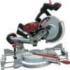
4. Once the desired miter angle is achieved, press down on the quick cam miter table lock to secure the table into position. 5. If the miter angle desired is NOT one of the ten positive stops noted above, simply lock the table at the desired angle by pressing down on the quick-cam miter table lock (2). Fig. HH fence must also be removed whenever a 45 ° bevel angle is desired with a miter angle greater than 22.5 °. Tilt the cutting head to the desired angle as shown on the bevel scale. The blade can be positioned at any angle, from a 90 ° straight cut (0° on the scale) to a 45 ° left and right bevel. Tighten the bevel lock handle (1) by pushing down to lock the cutting head in position. Bevel positive stops are provided at 0°, 33.9 ° and 45 °. Fig. II 2 1 BEVEL CUT (FIG. II) WARNING J • The sliding fence must be extended to the left or right when making bevel cuts.The sliding fence noted three bevel angles where the user must adjust the fences to match the degree of the bevel cut. Failure to extend the sliding fence will not allow enough space for the blade to pass through which could result in serious injury. At extreme miter or bevel angles the saw blade may also contact the fence. NOTE: The saw comes with a 33.9 ° bevel detent pin for setting up crown molding cuts when the angle of the walls equals 90 ° . • The right side sliding fence must be removed when making any right bevel angle cuts greater than 35 ° in combination with any right hand miter angle. This 36
-
 1
1 -
2
-
3
-
4
-
5
-
6
-
7
-
8
-
9
-
10
-
11
-
12
-
13
-
14
-
15
-
16
-
17
-
18
-
19
-
20
-
21
-
22
-
23
-
24
-
25
-
26
-
27
-
28
-
29
-
30
-
31
-
32
-
33
-
34
-
35
-
36
-
37
-
38
-
39
-
40
-
41
-
42
-
43
-
44
-
45
-
46
-
47
-
48
-
49
-
50
-
51
-
52
-
53
-
54
-
55
-
56
-
57
-
58
-
59
-
60
-
61
-
62
-
63
-
64
-
65
-
66
-
67
-
68
-
69
-
70
-
71
-
72
-
73
-
74
-
75
-
76
-
77
-
78
-
79
-
80
-
81
-
82
-
83
-
84
-
85
-
86
-
87
-
88
-
89
-
90
-
91
-
92
-
93
-
94
-
95
-
96
-
97
-
98
-
99
-
100
-
101
-
102
-
103
-
104
-
105
-
106
-
107
-
108
-
109
-
110
-
111
-
112
-
113
-
114
-
115
-
116
-
117
-
118
-
119
-
120
-
121
-
122
-
123
-
124
-
125
-
126
-
127
-
128
-
129
-
130
-
131
-
132
-
133
-
134
-
135
-
136
-
137
-
138
-
139
-
140
-
141
-
142
-
143
-
144
-
145
-
146
-
147
-
148
-
149
-
150
-
151
-
152
-
153
-
154
-
155
-
156
-
157
-
158
-
159
-
160
-
161
-
162
-
163
-
164
-
165
-
166
-
167
-
168
-
169
-
170
-
171
-
172
-
173
-
174
-
175
-
176
-
177
-
178
-
179
-
180
-
181
-
182
-
183
-
184
-
185
-
186
-
187
-
188
-
189
-
190
-
191
-
192
-
193
-
194
-
195
-
196
-
197
-
198
-
 199
199 -
 200
200 -
 201
201 -
 202
202 -
 203
203 -
 204
204 -
 205
205 -
 206
206 -
 207
207 -
 208
208 -
 209
209 -
210
-
211
-
212
-
213
-
214
-
215
-
216
-
217
-
218
-
219
-
220
-
221
-
222
-
223
-
224
 |
 |
