Craftsman 21221 Operation Manual - Page 188

saw has four mounting holes. Bolt
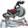
Page 188 highlights

1. To remove, loosen and remove the six screws (1) on the table inserts (2) with a Phillips screwdriver and remove the inserts. 2. To install, reposition the table inserts, install the six screws and tighten. 3. Check for blade clearance by moving the slide carriage through the full motion of the blade in the table slot. to the insulation or the wire connections resulting in electric shock or fire. • To avoid injury from flying debris, do not allow visitors to stand near the saw during any cutting operation. • Support the saw on a level work surface. • Bolt or clamp the saw to its support. Fig. I Mounting instructions 1. For stationary use, place the saw in the desired location, directly on a workbench where there is room for handling and proper support of the workpiece. The base of the saw has four mounting holes. Bolt the base of the miter saw (1) to the work surface (5), using the fastening method as shown in Fig J. MOUNTING THE MITER SAW (FIG. J, K) [_ WARNING J To avoid injury form unexpected saw movement: • Disconnect the power cord from the outlet, and lock the cutting head in the lower position using the stop latch. • Lock the slide carriage in place by tightening the slide carriage lock knob. • To avoid back injury, lift the saw by using the designated carrying handles located on the top of the machine. When lifting, bend at your knees, not from your back. • Never carry the miter saw by the power cord or by the switch handle. Carrying the tool by the Fig. J 1. Miter saw base 3 2. Hex head bolt 4 3. Rubber washer 4. Flat washer 1 Workbench 56. Flat washer 5 ---[--- Lockwasher 8. Hex nut 6 79. Jam nut 7 _9 _,: 8 NOTE: Mounting hardware is not included with this tool. Bolts, nuts, washers & screws must be purchased separately. 2. For portable use, place the saw on o aBo3l/t4thine. bthaiscek opfietchee omf itpelrywsoaowd. securely to the plywood using the mounting holes

  • 1
  • 2
  • 3
  • 4
  • 5
  • 6
  • 7
  • 8
  • 9
  • 10
  • 11
  • 12
  • 13
  • 14
  • 15
  • 16
  • 17
  • 18
  • 19
  • 20
  • 21
  • 22
  • 23
  • 24
  • 25
  • 26
  • 27
  • 28
  • 29
  • 30
  • 31
  • 32
  • 33
  • 34
  • 35
  • 36
  • 37
  • 38
  • 39
  • 40
  • 41
  • 42
  • 43
  • 44
  • 45
  • 46
  • 47
  • 48
  • 49
  • 50
  • 51
  • 52
  • 53
  • 54
  • 55
  • 56
  • 57
  • 58
  • 59
  • 60
  • 61
  • 62
  • 63
  • 64
  • 65
  • 66
  • 67
  • 68
  • 69
  • 70
  • 71
  • 72
  • 73
  • 74
  • 75
  • 76
  • 77
  • 78
  • 79
  • 80
  • 81
  • 82
  • 83
  • 84
  • 85
  • 86
  • 87
  • 88
  • 89
  • 90
  • 91
  • 92
  • 93
  • 94
  • 95
  • 96
  • 97
  • 98
  • 99
  • 100
  • 101
  • 102
  • 103
  • 104
  • 105
  • 106
  • 107
  • 108
  • 109
  • 110
  • 111
  • 112
  • 113
  • 114
  • 115
  • 116
  • 117
  • 118
  • 119
  • 120
  • 121
  • 122
  • 123
  • 124
  • 125
  • 126
  • 127
  • 128
  • 129
  • 130
  • 131
  • 132
  • 133
  • 134
  • 135
  • 136
  • 137
  • 138
  • 139
  • 140
  • 141
  • 142
  • 143
  • 144
  • 145
  • 146
  • 147
  • 148
  • 149
  • 150
  • 151
  • 152
  • 153
  • 154
  • 155
  • 156
  • 157
  • 158
  • 159
  • 160
  • 161
  • 162
  • 163
  • 164
  • 165
  • 166
  • 167
  • 168
  • 169
  • 170
  • 171
  • 172
  • 173
  • 174
  • 175
  • 176
  • 177
  • 178
  • 179
  • 180
  • 181
  • 182
  • 183
  • 184
  • 185
  • 186
  • 187
  • 188
  • 189
  • 190
  • 191
  • 192
  • 193
  • 194
  • 195
  • 196
  • 197
  • 198
  • 199
  • 200
  • 201
  • 202
  • 203
  • 204
  • 205
  • 206
  • 207
  • 208
  • 209
  • 210
  • 211
  • 212
  • 213
  • 214
  • 215
  • 216
  • 217
  • 218
  • 219
  • 220
  • 221
  • 222
  • 223
  • 224

1.
To remove, loosen and remove the
six screws
(1) on the table inserts
(2) with a Phillips screwdriver
and
remove the inserts.
2.
To install, reposition
the table
inserts, install the six screws and
tighten.
3.
Check for blade clearance
by
moving the slide carriage through
the full motion of the blade in the
table slot.
to the insulation
or the wire
connections
resulting
in electric
shock or
fire.
To avoid injury
from
flying
debris, do not allow visitors to
stand near the saw during any
cutting operation.
Support
the saw on a level work
surface.
Bolt or clamp the saw to its
support.
Fig. I
Mounting
instructions
1.
For stationary
use,
place the saw
in the
desired location, directly
on
a
workbench where there is
room
for handling and proper support
of the workpiece.
The base of the
saw has four mounting holes. Bolt
the base of the miter saw (1) to
the work surface (5), using the
fastening method as shown in Fig J.
MOUNTING
THE
MITER SAW
(FIG. J, K)
[_
WARNING
J
To avoid
injury
form
unexpected
saw movement:
Disconnect
the
power
cord
from
the
outlet,
and
lock
the cutting
head in
the
lower position using
the
stop latch.
Lock
the
slide
carriage
in place
by
tightening
the
slide
carriage
lock knob.
To avoid
back injury, lift
the
saw
by using
the
designated
carrying
handles located on
the top
of
the
machine. When
lifting, bend
at
your
knees, not from
your
back.
Never
carry
the
miter saw by
the
power
cord
or by
the
switch
handle.
Carrying
the tool
by
the
Fig. J
1.
3
2.
4
3.
4.
1
5.
---[---
_,
6.
5
_,:
7.
_9
6
8
8.
9.
7
NOTE:
Mounting
hardware
is not
included
with this tool.
Bolts,
nuts,
washers
& screws
must
be purchased
separately.
Miter saw base
Hex head bolt
Rubber washer
Flat washer
Workbench
Flat washer
Lockwasher
Hex nut
Jam nut
2.
For portable
use,
place the saw on
o
a 3/4 in. thick piece of plywood.
Bolt the base of the miter saw
securely to the
plywood using the mounting holes