D-Link DCS-2100G Product Manual - Page 9
Hardware Overview, Connections - support
 |
UPC - 790069274008
View all D-Link DCS-2100G manuals
Add to My Manuals
Save this manual to your list of manuals |
Page 9 highlights
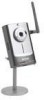
DCS-2100G User's Manual Hardware Overview Hardware Overview Connections Antenna Connector One antenna is included with the DCS-2100G. It is screwed onto the antenna connector on the side panel to provide a connection with a wireless network. DC Power Connector The DC power input connector is labeled DC 5V with a single jack socket to supply power to the DCS-2100G. Reset Button Reset will be initiated when the reset button is pressed once and Power LED begins to flash. Factory Reset will be initiated when the reset button is pressed continuously for ten seconds or when the Power LED begins to light up. Release the reset button and the Power LED will begin to flash indicating that the DCS-2100G's settings are reverting back to the factory settings. D-Link Systems, Inc. Ethernet Cable Connector The DCS-2100G features an RJ-45 connector for connections to 10Base-T Ethernet cabling or 100Base-TX Fast Ethernet cabling (which should be Category 5 UTP cable). The port supports the NWay protocol, allowing the DCS-2100G to automatically detect or negotiate the transmission speed of the network. 9
-
 1
1 -
2
-
3
-
 4
4 -
 5
5 -
 6
6 -
 7
7 -
 8
8 -
 9
9 -
 10
10 -
 11
11 -
 12
12 -
 13
13 -
 14
14 -
15
-
16
-
17
-
18
-
19
-
20
-
21
-
22
-
23
-
24
-
25
-
26
-
27
-
28
-
29
-
30
-
31
-
32
-
33
-
34
-
35
-
36
-
37
-
38
-
39
-
40
-
41
-
42
-
43
-
44
-
45
-
46
-
47
-
48
-
49
-
50
-
51
-
52
-
53
-
54
-
55
-
56
-
57
-
58
-
59
-
60
-
61
-
62
-
63
-
64
-
65
-
66
-
67
-
68
-
69
-
70
-
71
-
72
-
73
-
74
-
75
-
76
-
77
-
78
-
79
-
80
-
81
-
82
-
83
-
84
-
85
-
86
-
87
-
88
-
89
-
90
-
91
-
92
-
93
-
94
-
95
-
96
-
97
-
98
-
99
-
100
-
101
-
102
-
103
-
104
-
105
-
106
-
107
-
108
-
109
-
110
-
111
-
112
-
113
-
114
-
115
-
116
-
117
-
118
-
119
-
120
-
121
-
122
-
123
-
124
-
125
-
126
-
127
-
128
-
129
-
130
-
131
-
132
-
133
-
134
-
135
-
136
-
137
-
138
-
139
-
140
-
141
 |
 |
