D-Link DSN-656 User Manual
D-Link DSN-656 Manual
 |
View all D-Link DSN-656 manuals
Add to My Manuals
Save this manual to your list of manuals |
D-Link DSN-656 manual content summary:
- D-Link DSN-656 | User Manual - Page 1
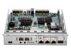
D-Link Document - User Manual D-Link Document - User Manual DSN-6200/6500 Series Version 1.00 December 2014 Copyright@2014 D-Link System, Inc. All Rights Reserved. 1 - D-Link DSN-656 | User Manual - Page 2
Copyright Copyright@2014, D-Link Corporation, Inc. All rights reserved. D-Link Document - User Manual Trademarks All products and trade names used in this manual are trademarks or registered trademarks of their respective companies. Default login information Management IP Address: 192.168.0.32 - D-Link DSN-656 | User Manual - Page 3
so may violate your warranty and expose you to electric shock. Refer all servicing to authorized service personnel. Please always follow the instructions in this user's manual. Tips and Cautions This manual uses the following symbols to draw attention to important safety and operational information - D-Link DSN-656 | User Manual - Page 4
D-Link Document - User Manual Conventions Bold [ ] square brackets { } braces | vertical bar / Slash underline Description Indicates text on a window, other than the window title, including menus, menu options, buttons, - D-Link DSN-656 | User Manual - Page 5
Contents Chapter 0 PREFACE...3 ABOUT THIS MANUAL ...3 TIPS AND CAUTIONS ...3 CONVENTIONS...3 Chapter 1 OVERVIEW ...10 PRODUCT OVERVIEW...10 Model Comparison...10 Package Contents...11 HARDWARE ...11 Front View...12 Disk Drive Assembly ...13 - D-Link DSN-656 | User Manual - Page 6
D-Link Document - User Manual Web UI ...32 HOW TO USE THE GUIDED CONFIGURATIONS ...35 Quick Installation Tool ...35 Volume Creation Wizard ...40 Chapter 4 BASIC CONFIGURATION ...44 INTERFACE HIERARCHY...44 SYSTEM CONFIGURATION ...46 System Settings ...47 Network Settings... - D-Link DSN-656 | User Manual - Page 7
D-Link Document - User Manual Volume Restoration ...88 Reboot and Shutdown ...89 PERFORMANCE MONITOR ...90 Disk...90 iSCSI...90 Chapter 5 ADVANCED OPERATIONS ...92 VOLUME REBUILD ...92 MIGRATE AND MOVE RAID - D-Link DSN-656 | User Manual - Page 8
D-Link Document - User Manual CLONE ...115 Setup Clone ...115 Start and Stop Clone ...116 Schedule Cases ...132 I/O Type ...134 Configuration ...136 Constraints ...137 Chapter 6 TROUBLESHOOTING ...138 SYSTEM BUZZER ...138 EVENT NOTIFICATIONS...138 Chapter 7 SOFTWARE APPLICATION...148 MICROSOFT - D-Link DSN-656 | User Manual - Page 9
D-Link Document - User Manual Setup MC/S ...149 Disconnect ...150 Chapter 8 Chapter 9 GLOSSARY AND ACRONYM LIST ...151 INDEX ...153 Copyright@2014 D-Link System, Inc. All Rights Reserved. 9 - D-Link DSN-656 | User Manual - Page 10
Overview D-Link Document - User Manual 1 Product Overview This user manual describes how to set up and use the D-Link DSN- and the glowing demand for data storage. D-Link storage systems can provide non-stop service with a high degree of fault tolerance by using D-link RAID technology and advanced - D-Link DSN-656 | User Manual - Page 11
D-Link Document - User Manual Package Contents The package contains the following items: D- Keys, screws for drives and rail kit (x1 packet) CD Quick Installation Guide Hardware This section provides basic information about the hardware components. Copyright@2014 D-Link System, Inc. All - D-Link DSN-656 | User Manual - Page 12
Front View D-Link Document - User Manual There is a power switch by the right front handle; a USB interface for a LCD screen by the left front handle. 1 2 3 Number 1 2 3 Description USB port: This is - D-Link DSN-656 | User Manual - Page 13
Manual Management IP Address: 192.168.0.32 User Name: admin Password: 123456 USB LCD comes as an optional device for the DSN-6200/6500 Series. The standard unit doesn't include an USB LCD. Both the USB port on the front left handle and the USB port on the controller itself support the - D-Link DSN-656 | User Manual - Page 14
D-Link Document - User Manual SAS Drive The front of each disk tray has four components: 3 4 SATA Drive 1 2 This table below provides details about the front components of a disk tray. - D-Link DSN-656 | User Manual - Page 15
SATA 6Gb/s SATA 3Gb/s SATA 1.5Gb/s 3TB SAS SAS 6Gb/s SAS 3Gb/s D-Link Document - User Manual SATA 6Gb/s SATA 3Gb/s SATA 6Gb/s SATA 3Gb/s SATA 6Gb/s SATA 1.5Gb/s Without MUX Board 2794 GB SAS 6Gb/s SAS 3Gb/s Rear View The following - D-Link DSN-656 | User Manual - Page 16
Number 1 2 3 4 5 6 7 8 9 LED D-Link Document - User Manual Description SAN ports DSN-6200: 6 x GbE iSCSI ports. DSN-6500: 2 x 10GbE iSCSI ports (SFP+) + 2 x GbE iSCSI ports. LEDs from right to left: Controller health LED: - D-Link DSN-656 | User Manual - Page 17
DSN-6200 (6 x GbE iSCSI) controller: 1 D-Link Document - User Manual 9 5 6 2 3 4 7 DSN-6500 (2 x 10GbE iSCSI (SFP+) + 2 x GbE iSCSI) controller: 1 9 5 6 2 3 DSN-6020 (6G SAS) JBOD controller: 4 7 7 2 7 RAID Concepts RAID is the abbreviation of Redundant Array of Independent - D-Link DSN-656 | User Manual - Page 18
D-Link Document - User Manual RAID Levels There are various RAID levels with different degrees of data protection, data availability, and performance. A description of supported RAID levels follow: Type RAID 0 RAID 1 N-way mirror RAID 3 RAID 5 RAID 6 RAID 0+1 RAID 10 RAID 30 RAID 50 RAID 60 JBOD - D-Link DSN-656 | User Manual - Page 19
D-Link Document - User Manual One RG (RAID group) consists of a set of VDs (Virtual Disk) and owns one RAID level attribute. Each RG can be divided into several VDs. - D-Link DSN-656 | User Manual - Page 20
D-Link Document - User Manual The target is the storage device itself or an appliance which controls and serves volumes or virtual volumes. The target is the device which performs - D-Link DSN-656 | User Manual - Page 21
Installation D-Link Document - User Manual 2 Installation Overview Before starting, prepare the following items: A management computer with a Gigabit Ethernet NIC (recommend) on the same network as the D-Link storage system. Connection - D-Link DSN-656 | User Manual - Page 22
D-Link Document - User Manual TIP: Install at least one drive in Slot 1 to 4 (marked gray slots). System event logs are saved in these drives. Otherwise, event logs no longer exist after a reboot. System Installation and Deployment Using the following instructions to install and deploy the storage - D-Link DSN-656 | User Manual - Page 23
D-Link Document - User Manual 。 Plug it into the chassis. 。 Install the Disk Drives. 。 Connect the management port cable and data port cables per the network plan, the topology examples for this are below. Copyright@2014 D-Link System, Inc. All Rights Reserved. 23 - D-Link DSN-656 | User Manual - Page 24
DSN-6200 series (DSN-6220): D-Link Document - User Manual DSN-6500 series (DSN-6520): Copyright@2014 D-Link System, Inc. All Rights Reserved. 24 - D-Link DSN-656 | User Manual - Page 25
JBOD DSN-6020: D-Link Document - User Manual Dual controller topology: For better data service availability, all the connections among hosts, switches, and the dual controllers are recommended to be redundant as shown below. Copyright@2014 D-Link System, Inc. All Rights Reserved. 25 - D-Link DSN-656 | User Manual - Page 26
D-Link Document - User Manual Console and UPS topology: Connect the console cable and UPS per the following. 。 Using RS-232 cable for console (back color, phone jack to DB9 - D-Link DSN-656 | User Manual - Page 27
D-Link Document - User Manual 。 Attach the power cords and power on the system, and then power on the hosts and the iSNS server (optional for iSCSI environment). 。 Start the - D-Link DSN-656 | User Manual - Page 28
D-Link Document - User Manual Power off the System If it becomes necessary to power down the system, it is recommended using a normal, controlled shutdown form through either the LCD - D-Link DSN-656 | User Manual - Page 29
Quick Setup D-Link Document - User Manual 3 Management Interfaces There are several management methods to manage the storage system, described on the following pages. Serial Console Use console cable (NULL modem cable) - D-Link DSN-656 | User Manual - Page 30
D-Link Document - User Manual TIP: D-Link systems support SSH for remote access only. When using SSH, the IP address and password are required for login. LCD After booting up the system, the following - D-Link DSN-656 | User Manual - Page 31
This table displays the LCD menu hierarchy. D-Link Document - User Manual Main L1 System Info. Alarm Mute L2 Firmware Version RAM Size MB Yes No Reset/ Shutdown Reset Shutdown Quick Install (only - D-Link DSN-656 | User Manual - Page 32
D-Link Document - User Manual Phy. Disk Temp. Enc. Management Cooling Reset to Default Power Supply Yes from the cache to the physical disks. Web UI D-Link storage systems support graphic user interface operation. They support most common web browsers. Be sure to connect the LAN cable to the - D-Link DSN-656 | User Manual - Page 33
D-Link Document - User Manual To access the Web UI, you have to enter a user name and password. The initial defaults for administrator login are: User Name: admin Password: 123456 - D-Link DSN-656 | User Manual - Page 34
D-Link Document - User Manual TIP: The Host Port Configuration menu bar option is only visible when the controller has multiple interfaces. The iSCSI Configuration menu bar option is only - D-Link DSN-656 | User Manual - Page 35
Document - User Manual How to Use the Guided Configurations To help users get started quickly, two guided configuration tools are advanced user, you can skip these steps. Quick Installation Tool This tool guides you through the process of setting up basic array information, configuring network - D-Link DSN-656 | User Manual - Page 36
D-Link Document - User Manual 3. Confirm or change the management port IP address and DNS server. If the default HTTP, HTTPS, and SSH port numbers are not allowed on your network, they can be changed here as well. Copyright@2014 D-Link System, Inc. All Rights Reserved. 36 - D-Link DSN-656 | User Manual - Page 37
D-Link Document - User Manual 4. For iSCSI Configurations, use this step to set up the data port iSCSI IP address, and then click the Next button. Copyright@2014 D-Link System, Inc. All Rights Reserved. 37 - D-Link DSN-656 | User Manual - Page 38
D-Link Document - User Manual 5. Choose a RAID Level. The number in the brackets is the maximum capacity at the RAID level. This step utilizes all drives in the storage system - D-Link DSN-656 | User Manual - Page 39
D-Link Document - User Manual 6. Verify all items, and then click the Finish button to complete the quick installation. Copyright@2014 D-Link System, Inc. All Rights Reserved. 39 - D-Link DSN-656 | User Manual - Page 40
D-Link Document - User Manual The iSCSI information is only displayed when iSCSI controllers are used. Use the Back button to return to a previous page to change any setting. Volume - D-Link DSN-656 | User Manual - Page 41
3. Select the default option Maximize the size of the RAID group or manual option Select the number of disks to use. From the drop-down list, select either the RAID Group capacity combination desired. Click Next button to - D-Link DSN-656 | User Manual - Page 42
D-Link Document - User Manual 5. Use LBA 64 support? It depends on the operation system. 6. Finally, verify the selections and click Finish button if they are correct. Copyright@2014 D-Link System, Inc. All Rights Reserved. 42 - D-Link DSN-656 | User Manual - Page 43
D-Link Document - User Manual The volume is created and named by the system automatically. It is available to use now. Copyright@2014 D-Link System, Inc. All Rights Reserved. 43 - D-Link DSN-656 | User Manual - Page 44
Basic Configuration D-Link Document - User Manual 4 Interface Hierarchy This table describes the hierarchy of / Date and Time / System Indication MAC Address / IP Address / DNS Server Address / Service Ports Login Options / Admin Password / User Password Email Settings / Send Test Mail SNMP Trap - D-Link DSN-656 | User Manual - Page 45
D-Link Document - User Manual Enclosure Management System Maintenance Virtual Disks Snapshots Logical Units Replication Hardware Monitor UPS SES S.M.A.R.T. System information Event log Upgrade Firmware Synchronization (This option is only - D-Link DSN-656 | User Manual - Page 46
Performance Monitor Quick Installation Volume Creation Wizard Reboot and Shutdown Disk iSCSI D-Link Document - User Manual Reboot / Shutdown Reboot options: Both Controller 1 and Controller 2 / Controller 1 / Controller 2 Show disk for: < -Local- | -JBODn- > Controller 1 / Controller 2 Step 1 / - D-Link DSN-656 | User Manual - Page 47
one. Date and Time: To change the current date, time and time zone settings, check Change Date and Time. The changes can be done manually or synchronized from an NTP (Network Time Protocol) server. System Identification: To Flash the status light on the front display for locating this system in - D-Link DSN-656 | User Manual - Page 48
D-Link Document - User Manual The options available on this tab are: Enable dual management DNS Server Address: If necessary, the IP address of DNS server can be entered or changed here. Service Ports: If the default port numbers of HTTP, HTTPS, and SSH are not allowed on the network, they - D-Link DSN-656 | User Manual - Page 49
D-Link Document - User Manual The options available on this tab are: Auto Logout: When the auto logout option is enabled, you will be logged out of the admin interface - D-Link DSN-656 | User Manual - Page 50
D-Link Document - User Manual You can also select which levels of event logs that you would like to receive. The default setting only includes Warning and Error event logs. - D-Link DSN-656 | User Manual - Page 51
D-Link Document - User Manual The options available on this tab are: SNMP Trap Settings: for receiving emails here. System Server Settings: Fill in the host address and the facility for syslog service. The default UDP port is 514. You can also check the alert levels here. There are some syslog - D-Link DSN-656 | User Manual - Page 52
D-Link Document - User Manual Most UNIX systems build in syslog daemon. Admin Interface and Front Display Alerts: You can check the alert level that will activate a pop-up message - D-Link DSN-656 | User Manual - Page 53
. Please consult your network switch user manual for VLAN setting instructions. Most of the work is done at the switch part. All you need to do is to make sure that your iSCSI port's VLAN ID matches that of switch port. If your network environment supports - D-Link DSN-656 | User Manual - Page 54
iSCSI data port. There are two options: Use DHCP to acquire an IP address automatically or Specify a Static IP Address to set the IP address manually. ▼ Make Default Gateway: Set the gateway of the IP address as default gateway. There can be only one default gateway. To remove the default - D-Link DSN-656 | User Manual - Page 55
D-Link Document - User Manual CAUTION: VLAN ID, jumbo frames for both the switching hub and view the entity name of the system, and setup iSNS IP for the iSNS (Internet Storage Name Service) protocol. It allows automated discovery, management and configuration of iSCSI devices on a TCP/IP network. - D-Link DSN-656 | User Manual - Page 56
D-Link Document - User Manual iSCSI Nodes The iSCSI Nodes tab is used to view the target name for iSCSI initiator. The two controllers support multiple nodes, listed below. DSN-6200 Series: support up to 64 multiple nodes per controller. DSN-6500 Series: support up to 64 multiple nodes per - D-Link DSN-656 | User Manual - Page 57
D-Link Document - User Manual 。 Click the OK button. 。 Check ▼ User. 。 Select the CHAP user(s) that will have access to the node. It can be more than one, but there - D-Link DSN-656 | User Manual - Page 58
D-Link Document - User Manual 。 Click OK button Rename Alias: Use this option to add or change iSCSI alias. 。 Select iSCSI sessions and their connection information. The DSN-6200/6500 Series supports up to 256 sessions per controller. Copyright@2014 D-Link System, Inc. All Rights Reserved. 58 - D-Link DSN-656 | User Manual - Page 59
D-Link Document - User Manual This table shows the column descriptions. Most of the output part of a bidirectional command. The default value is Yes. Immed. data (Immediate Data) sets the support for immediate data between the initiator and the target. Both must be set to the same setting. The - D-Link DSN-656 | User Manual - Page 60
Create User: Create a CHAP user. D-Link Document - User Manual 。 Enter the required information for User Name, Secret, and Re-type Secret. 。 If you would like this CHAP user to have access, select one or - D-Link DSN-656 | User Manual - Page 61
D-Link Document - User Manual Physical Disks The Physical Disks tab provides the status of the hard drives in the system. The two drop-down lists at the top enable - D-Link DSN-656 | User Manual - Page 62
D-Link Document - User Manual Serial Number Rate Write Cache Standby Read-Ahead Command Queuing Hard drive serial number. Hard drive rate: SAS 6.0Gb/s. SAS 3.0Gb/s. SATA 6.0Gb/s. SATA 3.0Gb/s. - D-Link DSN-656 | User Manual - Page 63
D-Link Document - User Manual 2. If there is any RAID group which is in protected RAID level and can be set with a dedicated spare disk, select one RAID group, and - D-Link DSN-656 | User Manual - Page 64
D-Link Document - User Manual Health RAID Current Controller (This option is only visible when status is online. These are for online disk roaming purpose Verify Parity: Regenerate parity for the RAID group. It supports the RAID level 3 / 5 / 6 / 30 / 50 / 60 Delete: Delete the RAID group Change - D-Link DSN-656 | User Manual - Page 65
D-Link Document - User Manual 。 Standby: Disabled: Disable auto spin down. (Default) 30 sec / 1 min / 5 min / 30 min: The hard drives will be spun down for power saving when the - D-Link DSN-656 | User Manual - Page 66
D-Link Document - User Manual Disks Used RAID Cell Status Health The number of physical disks in the RAID set. The number of RAID cells in the RAID set. The - D-Link DSN-656 | User Manual - Page 67
D-Link Document - User Manual 2. Enter a RAID Name for the RAID group. 3. Select a RAID Level from the drop-down list. 4. Click the Select Disks button to select disks from either - D-Link DSN-656 | User Manual - Page 68
D-Link Document - User Manual Virtual Disks The Virtual Disks tab is provided to File System: Enable SSD caching and set it as file system policy. Web Service: Enable SSD caching and set it as web service policy. Custom: Enable SSD caching and set it as customization policy. The right of - D-Link DSN-656 | User Manual - Page 69
D-Link Document - User Manual R % RAID LUN # Snapshot space (GB) or (MB) Snapshot # RAID Group for the virtual disk. Described in detail in chapter 5 Verify Parity: Execute parity check for the virtual disk. It supports RAID 3 / 5 / 6 / 30 / 50 / 60. The options are: 。 Verify and repair data - D-Link DSN-656 | User Manual - Page 70
D-Link Document - User Manual 。 Priority: High Priority (Default) Medium Priority. Low Priority. 。 Bg Rate: 4 / 3 / 2 / 1 / 0: Default value is 4. The higher number the background priority of a virtual disk has, the more - D-Link DSN-656 | User Manual - Page 71
1. Click Create button. D-Link Document - User Manual 2. Enter a Virtual Disk Name for the virtual disk. 3. Select a Data Storage from the drop-down list. 4. Enter your required Size. 5. Optionally, configure the following: 。 Stripe - D-Link DSN-656 | User Manual - Page 72
D-Link Document - User Manual partition. The options are Do Not Erase, erase First 1GB or Full Disk. The default value is Don Not Erase. 。 Space Reclaim: This option is - D-Link DSN-656 | User Manual - Page 73
D-Link Document - User Manual Used (GB) or (MB) Status Health Exposure Cache Mode LUN # Time Created The amount of the snapshot space that has been used. The unit can - D-Link DSN-656 | User Manual - Page 74
D-Link Document - User Manual 2. Select a Virtual Disk from the drop-down list. 3. Enter a Size which will be reserved for the snapshot space. 4. Click OK. The snapshot space is created. 5. - D-Link DSN-656 | User Manual - Page 75
D-Link Document - User Manual 12. Done. The Snapshot can be used. TIP: For DSN-6200/6500 Series, the maximum snapshot number per virtual disk is 64. Logical Units The - D-Link DSN-656 | User Manual - Page 76
D-Link Document - User Manual the controller has iSCSI ports.) The options available on this tab are: Attach LUN: Attach a logical unit number to the virtual disk. The options available - D-Link DSN-656 | User Manual - Page 77
D-Link Document - User Manual "iqn.host*" -> "iqn.host1" and "iqn.host12345" are accepted. This field cannot accept comma, so "iqn.host1, iqn.host2" stands a long string, not 2 iqns. TIP: - D-Link DSN-656 | User Manual - Page 78
D-Link Document - User Manual Connected: The replication task pair is connected. Reconnecting: The source is reconnecting to the target. The options available on this tab are: Create: Create a replication - D-Link DSN-656 | User Manual - Page 79
D-Link Document - User Manual Fan sensors: 10 seconds. When there are 3 errors consecutively, the system sends an ERROR event log. Power sensors: 10 seconds, when there are 3 errors consecutively, - D-Link DSN-656 | User Manual - Page 80
D-Link Document - User Manual For better protection and avoiding a single short period of high other vendors of UPS can work well, but they have no such communication features with the system. We support the traditional UPS via serial port and network UPS via SNMP. If using the UPS with a serial - D-Link DSN-656 | User Manual - Page 81
D-Link Document - User Manual Options UPS Type Shutdown Battery Level (%) Shutdown Delay (Seconds) reaches the set condition. Users should set these values carefully. SES The SES (SCSI Enclosure Services, one of the enclosure management standards) tab is used to enable or disable the management of - D-Link DSN-656 | User Manual - Page 82
D-Link Document - User Manual The options available on this tab are: Enable: Click the Enable vendors are different. Please refer to the hard drive vendors' specification for details. S.M.A.R.T. only supports SATA drives. SAS drives do not have this function and will show N/A in the web page - D-Link DSN-656 | User Manual - Page 83
D-Link Document - User Manual System Maintenance The System Maintenance menu accesses System Information, Event Log, Upgrade, Firmware Synchronization (This option is only visible when dual controllers are installed.), Reset - D-Link DSN-656 | User Manual - Page 84
D-Link Document - User Manual CAUTION: If you try to increase the system memory while running dual controller mode, please make sure both controllers have the same DIMM on each - D-Link DSN-656 | User Manual - Page 85
D-Link Document - User Manual The event logs are displayed in chronological order; the latest event log is on the first / top page. They are actually saved in the first - D-Link DSN-656 | User Manual - Page 86
, click the OK button to start upgrading the firmware. When upgrading, there is a progress bar running. After finished upgrading, the system must reboot manually to make the new firmware take effect. JBOD Firmware Update: To upgrade JBOD firmware, choose a JBOD first, the other steps are the same - D-Link DSN-656 | User Manual - Page 87
D-Link Document - User Manual If the firmware versions between two controllers are different, it will display the following message. Click the Apply button to synchronize. TIP: This tab is - D-Link DSN-656 | User Manual - Page 88
D-Link Document - User Manual The options available on this tab are: Import: Import all system configurations excluding volume configuration. Export: Export all configurations to a file. CAUTION: Import option will - D-Link DSN-656 | User Manual - Page 89
D-Link Document - User Manual Event Log The last event of the virtual disk. The options available on this tab are: Restore: Restore the virtual disk of the RAID group. - D-Link DSN-656 | User Manual - Page 90
D-Link Document - User Manual Performance Monitor The Performance Monitor menu option accesses the Disk and iSCSI. Disk The Disk displays the throughput and latency of the physical disk. Check - D-Link DSN-656 | User Manual - Page 91
D-Link Document - User Manual Copyright@2014 D-Link System, Inc. All Rights Reserved. 91 - D-Link DSN-656 | User Manual - Page 92
Advanced Operations D-Link Document - User Manual 5 Volume Rebuild If one physical disk of the RAID group which is set as protected RAID level (e.g.: RAID 5, or RAID 6) fails or has been removed, - D-Link DSN-656 | User Manual - Page 93
D-Link Document - User Manual Sometimes, rebuild is called recover; they are the same meaning. This table describes the relationship between RAID levels and recovery. Operation RAID 0 RAID 1 N-way mirror - D-Link DSN-656 | User Manual - Page 94
D-Link Document - User Manual There are some limitations when a RAID group is being migrated or moved. The system will reject these operations: 1. Add dedicated spare. 2. Remove a dedicated spare. 3. Create a - D-Link DSN-656 | User Manual - Page 95
D-Link Document - User Manual 4. Click the Select Disks button to select disks from either local or expansion JBOD systems, and click OK to complete the selection. The selected disks - D-Link DSN-656 | User Manual - Page 96
D-Link Document - User Manual 3. Change the virtual disk size. The size must be larger than the current, and then click the OK button to start extension. 4. Extension starts. If - D-Link DSN-656 | User Manual - Page 97
D-Link Document - User Manual Volume Volume Whole System Traditional Fat Provisioning Actual Physical Available space Thin provisioning sometimes is known as just-in-time capacity or over allocation. As - D-Link DSN-656 | User Manual - Page 98
D-Link Document - User Manual level of services with less hard drives purchased upfront, which can significantly reduce your total cost of ownership. Scalability: storage pool can grow on demand. When the storage - D-Link DSN-656 | User Manual - Page 99
D-Link Document - User Manual Figure 2: Virtual disks are created. In Figure 3, the free space of "Fat-RG" immediately reduces to 862GB. 1000GB is taken away by the virtual disk. - D-Link DSN-656 | User Manual - Page 100
D-Link Document - User Manual Snapshot space sits at the same RAID group of the volume that the snapshot is taken against. Therefore when you expose the snapshot into a virtual - D-Link DSN-656 | User Manual - Page 101
unused space and increase utilization rate. Automatic space reclamation will be automatically activated in RAID group initialization process or it can be set manually through capacity policy. You can set as many as 16 policies. When space usage ratio grows over the threshold set in the policy - D-Link DSN-656 | User Manual - Page 102
D-Link Document - User Manual entire volume will prevent the advantages of thin provisioning. with email systems, web-based archives, or regular file archive systems. When the number of supported volumes grows larger, the benefits of Thin provisioning will become more apparent. Disk Roaming Physical - D-Link DSN-656 | User Manual - Page 103
can support the RAID groups that are located in the local chassis. 3. Global spare disks can support all RAID groups that are located in different chassis. 4. When supporting has finished, the JBOD system must reboot manually to make the new firmware take effect. Copyright@2014 D-Link System, Inc. - D-Link DSN-656 | User Manual - Page 104
D-Link Document - User Manual MPIO and MC/S These features come from iSCSI initiator. They can be setup from the iSCSI initiator to establish redundant paths for sending I/O from the - D-Link DSN-656 | User Manual - Page 105
D-Link Document - User Manual Difference MC/S is implemented on iSCSI level, while MPIO of Windows XP, Windows Vista or Windows 7, then MC/S is the only option since Microsoft MPIO is supported in Windows Server editions only. 4. MC/S can provide higher throughput than MPIO in a Windows system, but - D-Link DSN-656 | User Manual - Page 106
D-Link Document - User Manual advantage of wide bandwidth, the I/O traffic remains operating until all physical links fail. If any link is restored, it will be added to the link - D-Link DSN-656 | User Manual - Page 107
D-Link Document - User Manual CAUTION: Before using trunking or LACP, the gigabit switch must support either trunking or LACP. Otherwise, the host cannot connect link with the storage device. Dual Controllers The D-Link storage system supports dual controllers of the same type for redundancy. - D-Link DSN-656 | User Manual - Page 108
D-Link Document - User Manual Ownership When creating a RAID group, it will be assigned with a preferred owner, the default owner is controller 1. To change the ownership of the RAID group, - D-Link DSN-656 | User Manual - Page 109
D-Link Document - User Manual ownership of RAID group will switch to the working controller. For example, if controller 1, which owns the RAID group 1 fails accidently, the ownership of RAID - D-Link DSN-656 | User Manual - Page 110
D-Link Document - User Manual Snapshots Snapshot-on-the-box captures the instant state of data in the target volume in a logical sense. The underlying logic is Copy-on-Write, - D-Link DSN-656 | User Manual - Page 111
D-Link Document - User Manual 5. Set quota to expose the snapshot. Click ▼ -> Set Quota option. 6. Enter the size reserved for the snapshot. If the size is zero, the exposed snapshot - D-Link DSN-656 | User Manual - Page 112
D-Link Document - User Manual Schedule Snapshots The snapshots can be taken by schedule such as hourly or daily. Please follow the procedures. 1. There are two methods to set schedule - D-Link DSN-656 | User Manual - Page 113
D-Link Document - User Manual CAUTION: Before executing rollback, it is better that the not on the disk, then the snapshot may have an incomplete image of the original data. The problem does not belong to the storage device. To avoid this data inconsistency issue between snapshot and original data - D-Link DSN-656 | User Manual - Page 114
develops VSS (volume shadow copy service) to prevent this issue. snapshot doesn't have the problem of data-inconsistencies. For more The DSN6200/6500 storage system can support Microsoft VSS. What if there so on. 2. If the snapshot is taken manually, when taking the 65th snapshot it will fail and - D-Link DSN-656 | User Manual - Page 115
D-Link Document - User Manual Rollback and delete snapshot When a snapshot has been rolled back, the related snapshots which are earlier than it will also be removed. But the remaining - D-Link DSN-656 | User Manual - Page 116
D-Link Document - User Manual 4. At this time, if the source virtual disk has no snapshot space, it will allocate snapshot space for clone usage automatically. The size will depend - D-Link DSN-656 | User Manual - Page 117
D-Link Document - User Manual TIP: Daily clones will be taken at every 00:00. Weekly clones will be taken every Sunday 00:00. Monthly clones will be taken the - D-Link DSN-656 | User Manual - Page 118
Select the source virtual disk, and then click ▼ -> Clear Clone. 2. Click OK button to clear clone job. Clone Constraint While the clone is processing manually, the increment data of the virtual disk is over the snapshot space. The clone will complete the task, but the clone snapshot will fail. The - D-Link DSN-656 | User Manual - Page 119
clone by user Run out of snapshot space Auto delete old clone snapshot Auto restart an hour later Start clone process with fully copy Manually release snapshot space Restart clone by user Done Replication The replication function can replicate data easily through LAN or WAN from one system to - D-Link DSN-656 | User Manual - Page 120
D-Link Document - User Manual Figure 1: Source Side Figure 2: Target Side 2. After creating the target virtual disk, please also setup snapshot space. The snapshot of the source virtual disk can - D-Link DSN-656 | User Manual - Page 121
D-Link Document - User Manual 8. Choose Authentication Method and input the CHAP user if needed. Select a Target Node, and then click the Next button. 9. Select a Target LUN. When a replication job - D-Link DSN-656 | User Manual - Page 122
D-Link Document - User Manual Start and Stop Replication Task To start replication task, please follow procedure below. 1. In Replications tab of the source side, select the source virtual disk, - D-Link DSN-656 | User Manual - Page 123
D-Link Document - User Manual 2. Select the Source Port and input the Target IP, and then click OK button. 3. The connection is added. To delete multi connections per session of - D-Link DSN-656 | User Manual - Page 124
D-Link Document - User Manual 2. Select a Shaping Group to setup. 3. Input the bandwidth (MB) at the Peak time. 4. If needed, check Enable Off-Peak, and then input the bandwidth (MB) - D-Link DSN-656 | User Manual - Page 125
D-Link Document - User Manual 2. Check the schedules that you want. They can be set by monthly, weekly, daily, or hourly. Click OK to apply. TIP: Daily replication will be - D-Link DSN-656 | User Manual - Page 126
value of our suggestion. If the user sets the snapshot space manually and lower than the default value, the user should be aware that button to delete the replication task. Clone Transfers to Replication It is always a problem doing a full copy over LAN or WAN when the replication task is executed - D-Link DSN-656 | User Manual - Page 127
D-Link Document - User Manual 1. Skip full copy on a new, clean virtual disk. The term "clean" means that the virtual disk has never had data written on it since created. - D-Link DSN-656 | User Manual - Page 128
D-Link Document - User Manual CAUTION: Changing a cloning job to a replication task is only available when the cloning job has been finished. This change is irreversible. 5. Deactivate the RAID group - D-Link DSN-656 | User Manual - Page 129
D-Link Document - User Manual Fast Rebuild When executing rebuild, the Fast Rebuild feature skips any partition of the virtual disk where no write changes have occurred, it will focus - D-Link DSN-656 | User Manual - Page 130
D-Link Document - User Manual Configuration When creating a virtual disk, enable the Fast Rebuild. The default is disabled. Constraint Here are some constraints about Fast Rebuild. Only thick/fat RAID group supports this feature. Thin provision RAID group already has this feature implemented. - D-Link DSN-656 | User Manual - Page 131
D-Link Document - User Manual needs to be as high as possible. In recent years, the capacity of HDDs has increased but their random input/output (I/O) has not increased at - D-Link DSN-656 | User Manual - Page 132
D-Link Document - User Manual Populating the Cache The actions that read data from the HDD and write to the SSD are called populating the cache. It is a background operation - D-Link DSN-656 | User Manual - Page 133
D-Link Document - User Manual 1. Request Read 3. Return Data Memory Cache Data 4. Populate Cache 2. Read from HDD SSD HDD The following steps describe details about a host read with a cache miss: 1. A - D-Link DSN-656 | User Manual - Page 134
D-Link Document - User Manual The following steps describe details about a host read with a cache hit: -read threshold, and populate-on-write threshold. Three pre-defined I/O types are supported; they are database, file system, and web service. The user can select an I/O type to set the SSD cache of - D-Link DSN-656 | User Manual - Page 135
D-Link Document - User Manual the application to get the best performance. If the above three applications are not suitable, the last item is customization which you may set the configurations by yourself. I/O Type Database File System Web Service Customization Block Size (Sectors) 1MB (2,048) 2MB - D-Link DSN-656 | User Manual - Page 136
up time, at least. T = (C * P) / (I * S * D) D-Link Document - User Manual The real case may be longer than the estimate time. Here we take an example of the following. I: 250 IOPS (Random IOPS per HDD) S: 64KB (Web service) D: 16 HDDs C: 480GB (1 SSD) P: 2 (Populate-on-read threshold - D-Link DSN-656 | User Manual - Page 137
- User Manual Constraints Here are some constraints about SSD caching. Only SSD can be used for SSD caching space of a virtual disk. A SSD can be assigned to one and only one virtual disk as its caching space. Up to 8 SSDs can be used as a SSD cache of a virtual disk. Support up to - D-Link DSN-656 | User Manual - Page 138
Troubleshooting D-Link Document - User Manual 6 System Buzzer The system buzzer features are listed below: The system buzzer initiates for 1 second when system boots up successfully. The system buzzer initiates continuously - D-Link DSN-656 | User Manual - Page 139
D-Link Document - User Manual INFO INFO ERROR ERROR ERROR ERROR ERROR ERROR ERROR ERROR ERROR ERROR ERROR INFO INFO INFO INFO INFO INFO ECC none SCSI bus reset SCSI - D-Link DSN-656 | User Manual - Page 140
D-Link Document - User Manual ERROR ERROR INFO WARNING ERROR ERROR Voltage level 2 shutdown Voltage level 2 CTR shutdown UPS OK UPS fail UPS AC loss UPS power low WARNING SMART T.E.C. - D-Link DSN-656 | User Manual - Page 141
move of VD . LUN is attached to VD . LUN is detached from VD . RG has been manually activated. RG has been manually deactivated. Rewrite at LBA of VD starts. Rewrite at LBA of VD completes. Rewrite at LBA - D-Link DSN-656 | User Manual - Page 142
D-Link Document - User Manual ERROR INFO INFO WARNING WARNING WARNING WARNING WARNING WARNING INFO INFO INFO INFO INFO INFO INFO INFO INFO INFO WARNING INFO WARNING ERROR ERROR ERROR - D-Link DSN-656 | User Manual - Page 143
D-Link Document - User Manual INFO INFO WARNING INFO Snap rollback started Snap rollback finished Snap quota reached Snap clear space Snapshot rollback of VD has been started. Snapshot - D-Link DSN-656 | User Manual - Page 144
D-Link Document - User Manual WARNING INFO WARNING WARNING INFO INFO ERROR ERROR DEBUG WARNING INFO INFO WARNING INFO WARNING INFO WARNING WARNING WARNING WARNING INFO WARNING WARNING WARNING WARNING - D-Link DSN-656 | User Manual - Page 145
D-Link Document - User Manual INFO INFO ERROR ERROR ERROR ERROR ERROR ERROR ERROR ERROR PD RPS finished F2L PD RPS finished F2F PD RPS failed L2F PD RPS failed - D-Link DSN-656 | User Manual - Page 146
D-Link Document - User Manual Level INFO INFO INFO INFO INFO INFO ERROR ERROR ERROR ERROR ERROR ERROR ERROR ERROR ERROR INFO Type RG owner changed Force CTR write through - D-Link DSN-656 | User Manual - Page 147
D-Link Document - User Manual INFO INFO WARNING WARNING WARNING VD replication set VD replication reset Auto rep not enable Auto rep error Auto rep no snap INFO INFO INFO - D-Link DSN-656 | User Manual - Page 148
Software Application D-Link Document - User Manual 7 Microsoft iSCSI Initiator Here is the step by step process to setup Microsoft iSCSI Initiator. Please visit Microsoft website for the latest iSCSI initiator. This - D-Link DSN-656 | User Manual - Page 149
D-Link Document - User Manual Setup MPIO 1. If running MPIO, please continue. 2. Click Discovery tab to connect the second path. 3. Click Discover Portal button. Enter the IP address or DNS - D-Link DSN-656 | User Manual - Page 150
D-Link Document - User Manual 9. Done. Disconnect 1. Select the target name, click Disconnect button, and then click Yes button. 2. Done, the iSCSI device disconnected successfully. Copyright@2014 D-Link System, Inc. All Rights Reserved. 150 - D-Link DSN-656 | User Manual - Page 151
D-Link Document - User Manual Glossary and Acronym List Common Terminology Item RAID PD RG VD LUN GUI RAID cell WT WB RO DS LS GS Description Redundant Array of - D-Link DSN-656 | User Manual - Page 152
- User Manual DG SCSI Reporting Technology World Wide Name Host Bus Adapter SCSI Enclosure Services Network Interface Card Battery Backup Module iSCSI / SAS Terminology management requirements for an enclosure controller slot that will support a variety of storage controllers from a variety of - D-Link DSN-656 | User Manual - Page 153
D-Link Document - User Manual Index A Active Sessions 58 Connection Details 59 Disconnect 59 B BBM Nodes 56 Authentication Method 56 Change Portal 57 Rename Alias 58 iSNS (Internet Storage Name Service 55 J JBOD Expansion 102 Connecting JBOD 102 Upgrade Firmware 103 Jumbo Frame 54 L - D-Link DSN-656 | User Manual - Page 154
D-Link Document - User Manual Device Buzzer 52 Log and Alert Settings 50 Admin Interface 47 DNS Server Address 48 Enable dual management ports 48 IP Address 48 MAC Address 48 Service Ports 48 Network Setup 52 Disable Jumbo Frames 54 Enable Jumbo Frames 54 iSCSI Bonding Settings 53 - D-Link DSN-656 | User Manual - Page 155
85 Controller Mode 86, 109 Controller Module Firmware Update 86 JBOD Firmware Update 86, 103 UPS (Uninterruptible Power Supply 80 D-Link Document - User Manual V Virtual Disks 68 Attach LUN 70, 73, 75 Change Replication Options 70 Cleanup Snapshots 70, 73 Clear Clone 70 Cloning Options 69
-
 1
1 -
 2
2 -
 3
3 -
 4
4 -
 5
5 -
 6
6 -
 7
7 -
8
-
9
-
10
-
11
-
12
-
13
-
14
-
15
-
16
-
17
-
18
-
19
-
20
-
21
-
22
-
23
-
24
-
25
-
26
-
27
-
28
-
29
-
30
-
31
-
32
-
33
-
34
-
35
-
36
-
37
-
38
-
39
-
40
-
41
-
42
-
43
-
44
-
45
-
46
-
47
-
48
-
49
-
50
-
51
-
52
-
53
-
54
-
55
-
56
-
57
-
58
-
59
-
60
-
61
-
62
-
63
-
64
-
65
-
66
-
67
-
68
-
69
-
70
-
71
-
72
-
73
-
74
-
75
-
76
-
77
-
78
-
79
-
80
-
81
-
82
-
83
-
84
-
85
-
86
-
87
-
88
-
89
-
90
-
91
-
92
-
93
-
94
-
95
-
96
-
97
-
98
-
99
-
100
-
101
-
102
-
103
-
104
-
105
-
106
-
107
-
108
-
109
-
110
-
111
-
112
-
113
-
114
-
115
-
116
-
117
-
118
-
119
-
120
-
121
-
122
-
123
-
124
-
125
-
126
-
127
-
128
-
129
-
130
-
131
-
132
-
133
-
134
-
135
-
136
-
137
-
138
-
139
-
140
-
141
-
142
-
143
-
144
-
145
-
146
-
147
-
148
-
149
-
150
-
151
-
152
-
153
-
154
-
155
 |
 |

D-Link Document – User Manual
D-Link Document - User Manual
DSN-6200/6500 Series
Version 1.00
December 2014
1
Copyright@2014 D-Link System, Inc. All Rights Reserved.