D-Link DWS-3024L User Manual - Page 35
Wiring Closet Topology
 |
View all D-Link DWS-3024L manuals
Add to My Manuals
Save this manual to your list of manuals |
Page 35 highlights
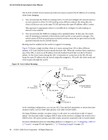
2 Planning the D-Link Unified Access System Network equipment such as hubs, routers, or other switches directly to the 10/100/1000 Mbps Ethernet ports on the switch. All connections to the D-Link Unified Switch must be wired connections since the switch does not have any radios. In Figure 8, the D-Link Unified Switches are both LAN and WLAN switches that handle traffic from end users connected to the wired LAN as well as traffic from the D-Link Access Points. In the diagram, Building 1 and Building 2 have a D-Link Unified Switch on each floor. Figure 8. Wiring Closet Topology Building 1 Floor 2 AAPPs s Unified Switch Unified Switch Unified Switch Unified Switch Building 2 Floor 2 L2/L3 Distribution Switch APs APs Building 1 Floor 1 APs APs Unified Switch Unified Switch To Network Backbone Building 2 Floor 1 APs APs The four D-Link Unified Switches are in the same peer group. This allows wireless clients to roam between floors and between buildings without the need to re-authenticate. Additionally, each Unified Switch shares its list of managed APs and wireless clients with the switches in the peer group so that the APs and wireless clients are not reported as rogues (unknown). The topology in Figure 8 works well if you need to add, upgrade, or replace LAN switches on your network. NOTE: When tunneled clients are used in conjunction with peer switches, one of the peer switches must be configured as a default gateway for the tunneled clients. Normally the default gateway routes all traffic from the client's subnet to other subnets, however in a peer switch network the Unified Switch that manages the AP to which the client is associated routes the frames into the remote subnets. This means that each peer switch must have routing table entries that enable it to route frames to every subnet in the network. WLAN Topology Considerations 35
-
 1
1 -
2
-
3
-
4
-
5
-
6
-
7
-
8
-
9
-
10
-
11
-
12
-
13
-
14
-
15
-
16
-
17
-
18
-
19
-
20
-
21
-
22
-
23
-
24
-
25
-
26
-
27
-
28
-
29
-
 30
30 -
 31
31 -
 32
32 -
 33
33 -
 34
34 -
 35
35 -
 36
36 -
 37
37 -
 38
38 -
 39
39 -
 40
40 -
41
-
42
-
43
-
44
-
45
-
46
-
47
-
48
-
49
-
50
-
51
-
52
-
53
-
54
-
55
-
56
-
57
-
58
-
59
-
60
-
61
-
62
-
63
-
64
-
65
-
66
-
67
-
68
-
69
-
70
-
71
-
72
-
73
-
74
-
75
-
76
-
77
-
78
-
79
-
80
-
81
-
82
-
83
-
84
-
85
-
86
-
87
-
88
-
89
-
90
-
91
-
92
-
93
-
94
-
95
-
96
-
97
-
98
-
99
-
100
-
101
-
102
-
103
-
104
-
105
-
106
-
107
-
108
-
109
-
110
-
111
-
112
-
113
-
114
-
115
-
116
-
117
-
118
-
119
-
120
-
121
-
122
-
123
-
124
-
125
-
126
-
127
-
128
-
129
-
130
-
131
-
132
-
133
-
134
-
135
-
136
-
137
-
138
-
139
-
140
-
141
-
142
-
143
-
144
-
145
-
146
-
147
-
148
-
149
-
150
-
151
-
152
-
153
-
154
-
155
-
156
-
157
-
158
-
159
-
160
-
161
-
162
-
163
-
164
-
165
-
166
-
167
-
168
-
169
-
170
-
171
-
172
-
173
-
174
-
175
-
176
-
177
-
178
-
179
-
180
-
181
-
182
-
183
-
184
-
185
-
186
-
187
-
188
-
189
-
190
-
191
-
192
-
193
-
194
-
195
-
196
-
197
-
198
-
199
-
200
-
201
-
202
-
203
-
204
-
205
-
206
-
207
-
208
-
209
-
210
-
211
-
212
-
213
-
214
-
215
-
216
-
217
-
218
-
219
-
220
-
221
-
222
-
223
-
224
-
225
-
226
-
227
-
228
-
229
-
230
-
231
-
232
-
233
-
234
-
235
-
236
-
237
-
238
-
239
-
240
-
241
-
242
-
243
-
244
-
245
-
246
-
247
-
248
-
249
-
250
-
251
-
252
-
253
-
254
-
255
-
256
-
257
-
258
-
259
-
260
-
261
-
262
-
263
-
264
-
265
-
266
-
267
-
268
 |
 |
