D-Link DWS-3160-24TC DWS-3160 Series Hardware Installation Guide - Page 13
Rear Panel Description, Power, Console, Link/Act LEDs, PoE LED Mode, DWS-3160-24PC Only
 |
View all D-Link DWS-3160-24TC manuals
Add to My Manuals
Save this manual to your list of manuals |
Page 13 highlights
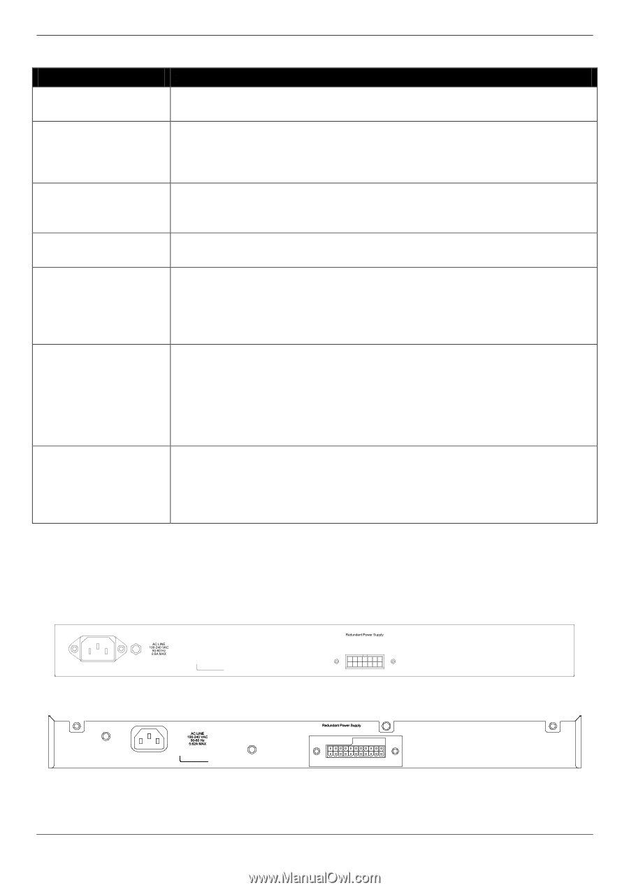
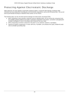
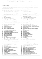
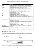
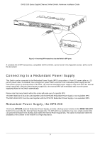
DWS-3160 Series Gigabit Ethernet Unified Switch Hardware Installation Guide LED Power Console RPS Fan SD Link/Act LEDs PoE LED Mode (DWS-3160-24PC Only) Description This LED will light solid green after the Switch has been powered on successfully. This LED will be off when the Switch is no longer receiving power (i.e. powered off). This LED will blink green during the Power-On Self Test (POST). This LED will light solid green when a user is logged in through the console port. This LED will be off after the POST finished successfully and no user is connected to the console port. This LED will light solid green if the Redundant Powers Supply is in use. This LED will blink green when the Switch detects that the RPS is connected. This LED will be off when the RPS is not in use. This LED will blink red when a fan fails. This LED will be off when all the fans are working properly. This LED will light solid green if a Secure Digital (SD) card is plugged in. This LED will blink green when the Switch is reading or writing data to and from the SD card. This LED will be off when no SD card is plugged into the SD port. This LED will light solid red when an SD card failure has been detected. This LED will light solid green when there is a secure connection to a 1000Mbps Ethernet device at any of the ports. This LED will light solid orange when there is a secure connection to a 10/100Mbps Ethernet device at any of the ports. This LED will blink green when a 1000Mbps port is active, or blink orange when a 10/100Mbps port is active. This LED will be off when there is no link or activity. This LED will light solid green when the port is feeding power to the PoE devices plugged in. This LED will light solid orange when the port is in an error condition state. This LED will be off when the port is not supplying power to the device plugged in. After the pressing the 'Mode' button, only the port LEDs, that feed power, will be lit. Rear Panel Description The Rear panel of the Switch consists of a power connector and an outlet for an external redundant power supply. Figure 1- 5. Rear panel view of the DWS-3160-24TC Figure 1- 6. Rear panel view of the DWS-3160-24PC Connect the one end of the power cord supplied to the power connector and the other end into a properly grounded electrical outlet. The Switch will automatically adjust the power setting to adapt to any voltage supply in the range from 5
-
 1
1 -
2
-
3
-
4
-
5
-
6
-
7
-
 8
8 -
 9
9 -
 10
10 -
 11
11 -
 12
12 -
 13
13 -
 14
14 -
 15
15 -
 16
16 -
 17
17 -
 18
18 -
19
-
20
-
21
-
22
-
23
-
24
-
25
-
26
-
27
-
28
-
29
-
30
-
31
-
32
-
33
-
34
-
35
-
36
-
37
-
38
-
39
-
40
-
41
-
42
-
43
-
44
-
45
-
46
-
47
-
48
-
49
-
50
-
51
-
52
-
53
-
54
-
55
-
56
-
57
-
58
-
59
-
60
-
61
-
62
-
63
-
64
-
65
-
66
-
67
 |
 |