D-Link DWS-3160-24TC DWS-3160 Series Hardware Installation Guide - Page 14
Side Panel Description, DPS-200, DWS-3124-24TC
 |
View all D-Link DWS-3160-24TC manuals
Add to My Manuals
Save this manual to your list of manuals |
Page 14 highlights
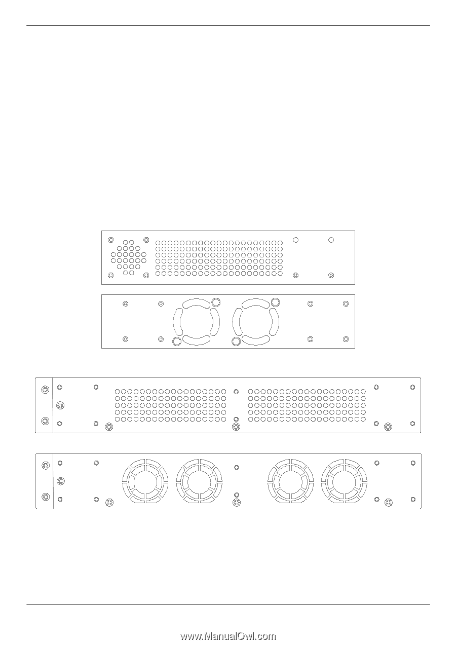
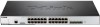
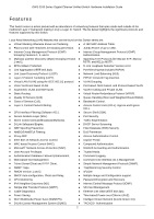
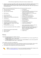
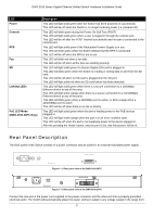
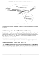
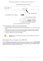
DWS-3160 Series Gigabit Ethernet Unified Switch Hardware Installation Guide 100~240VAC at 50~60Hz. In addition, an optional external Redundant Power Supply (DPS-200 for the DWS-3124-24TC and DPS-700 for the DWS-3124-24PC) can be plugged into the connector displayed above. When the internal power fails, this optional external RPS will take over all the power immediately and automatically. In the event that a power failure might occur in the environment and no UPS is used, as a precaution, unplug the power cord from the Switch. After the return of power, you can plug the power cord back into the Switch's power connector. Side Panel Description The Side panel of the Switch consists out of heat and fan vents that are used to dissipate heat. Do not block these openings. Leave at least 4 inches of space at the rear and sides of the Switch for proper ventilation. Be reminded that without proper heat dissipation and air circulation, system components might overheat, which could lead to system failure or even severely damage components. Figure 1- 7. Side panels of the DWS-3160-24TC Figure 1- 8. Side panels of the DWS-3160-24PC 6
-
 1
1 -
2
-
3
-
4
-
5
-
6
-
7
-
8
-
 9
9 -
 10
10 -
 11
11 -
 12
12 -
 13
13 -
 14
14 -
 15
15 -
 16
16 -
 17
17 -
 18
18 -
 19
19 -
20
-
21
-
22
-
23
-
24
-
25
-
26
-
27
-
28
-
29
-
30
-
31
-
32
-
33
-
34
-
35
-
36
-
37
-
38
-
39
-
40
-
41
-
42
-
43
-
44
-
45
-
46
-
47
-
48
-
49
-
50
-
51
-
52
-
53
-
54
-
55
-
56
-
57
-
58
-
59
-
60
-
61
-
62
-
63
-
64
-
65
-
66
-
67
 |
 |