Dell Alienware x15 R2 Service Manual
Dell Alienware x15 R2 Manual
 |
View all Dell Alienware x15 R2 manuals
Add to My Manuals
Save this manual to your list of manuals |
Dell Alienware x15 R2 manual content summary:
- Dell Alienware x15 R2 | Service Manual - Page 1
Alienware x15 R2 Service Manual Regulatory Model: P111F Regulatory Type: P111F003 December 2021 Rev. A00 - Dell Alienware x15 R2 | Service Manual - Page 2
use of your product. CAUTION: A CAUTION indicates either potential damage to hardware or loss of data and tells you how to avoid the problem. WARNING: A WARNING indicates a potential for property damage, personal injury, or death. © 2022 Dell Inc. or its subsidiaries. All rights reserved. Dell, EMC - Dell Alienware x15 R2 | Service Manual - Page 3
computer...5 Safety instructions...5 Electrostatic discharge-ESD protection...6 ESD field service kit ...6 After working inside your computer...7 Chapter 2: Removing and installing components 8 Recommended tools...8 Screw list...8 Major components of Alienware x15 R2...9 Disassembly and reassembly - Dell Alienware x15 R2 | Service Manual - Page 4
BIOS in Windows...69 Updating the BIOS using the USB drive in Windows 70 Chapter 5: Troubleshooting...71 Handling swollen Lithium-ion batteries...71 Locate the Service Tag or Express Service Code of your Dell computer 71 System-diagnostic lights...71 SupportAssist diagnostics...72 Recovering the - Dell Alienware x15 R2 | Service Manual - Page 5
and the contacts. CAUTION: You should only perform troubleshooting and repairs as authorized or directed by the Dell technical assistance team. Damage due to servicing that is not authorized by Dell is not covered by your warranty. See the safety instructions that is shipped with the product or at - Dell Alienware x15 R2 | Service Manual - Page 6
may not be obvious, such as intermittent problems or a shortened product life span. As more difficult type of damage to recognize and troubleshoot is the intermittent (also called latent or and the hardware is known as bonding. Use only Field Service kits with a wrist strap, mat, and bonding wire. - Dell Alienware x15 R2 | Service Manual - Page 7
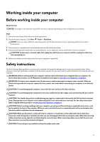
plastic heat sink casings, away from internal parts that are insulators and often highly charged. ● Working Environment - Before deploying the ESD Field Service kit, assess the situation at the customer location. For example, deploying the kit for a server environment is different than for a desktop - Dell Alienware x15 R2 | Service Manual - Page 8
Removing and installing components NOTE: The images in this document may differ from your computer depending on the configuration you ordered. Recommended tools The procedures in this document may require the following tools: ● Phillips screwdriver #0 ● Plastic scribe Screw list NOTE: When - Dell Alienware x15 R2 | Service Manual - Page 9
and keyboard assembly Palm-rest and keyboard assembly M1.6x1.8 M1.2x1.5 Power-button bracket Palm-rest and keyboard assembly M2x1.9 Quantity 2 4 2 2 2 5 2 5 9 4 2 2 Major components of Alienware x15 R2. The following image shows the major components of - Dell Alienware x15 R2 | Service Manual - Page 10
1. Rear I/O-cover 2. Tron-light cable 3. Base cover 4. I/O board 5. Power-adapter port 6. Right fan 7. System board 8. Battery 9. Touchpad 10. Right speaker 11. Display assembly 12. Left speaker 13. Keyboard-controller board 14. Wireless card 15. solid-state drive 16. Left fan 17. Fan and heat-sink - Dell Alienware x15 R2 | Service Manual - Page 11
Disassembly and reassembly NOTE: The images in this document may differ from your computer depending on the configuration you ordered. Base cover Removing the base cover Prerequisites 1. Follow the procedure in Before working inside your computer. About this task NOTE: Before removing the base cover - Dell Alienware x15 R2 | Service Manual - Page 12
12 - Dell Alienware x15 R2 | Service Manual - Page 13
Steps 1. Remove the four screws (M2.5x7) that secure the base cover to the palm-rest and keyboard assembly. 2. Loosen the two captive screws (M2.5x7) that secure the base cover to the palm-rest and keyboard assembly. 3. Using a plastic scribe, pry the base cover from the gap created after loosening - Dell Alienware x15 R2 | Service Manual - Page 14
14 - Dell Alienware x15 R2 | Service Manual - Page 15
cable to the system board and route the cable through the routing guides on the fan. 2. Slide the tabs on the top of kind to pry on or against the battery. ● Ensure any screws during the servicing of this product are not lost or misplaced, to prevent accidental puncture or damage to the battery - Dell Alienware x15 R2 | Service Manual - Page 16
release it as puncturing, bending, or crushing a lithium-ion battery can be dangerous. In such an instance, contact Dell technical support battery. After a service incident where the date and time. The computer starts functioning normally after setting the date from the routing guides on the fan - Dell Alienware x15 R2 | Service Manual - Page 17
. 3. Replace the four screws (M2x4) that secure the battery to the palm-rest and keyboard assembly. 4. Route the battery cable through the routing guides on the fan and connect the battery cable to the system board. Next steps 1. Install the base cover. 2. Follow the procedure in After working - Dell Alienware x15 R2 | Service Manual - Page 18
to pry on or against the battery. ● Ensure any screws during the servicing of this product are not lost or misplaced, to prevent accidental puncture or to release it as puncturing, bending, or crushing a lithium-ion battery can be dangerous. In such an instance, contact Dell technical support for - Dell Alienware x15 R2 | Service Manual - Page 19
About this task The following image indicates the location of the battery cable and provides a visual representation of the installation procedure. Steps 1. Align and adhere the battery cable to the battery. 2. Connect the battery cable to the connector on the battery. Next steps 1. Install the - Dell Alienware x15 R2 | Service Manual - Page 20
Steps 1. Remove the screw (M2x3) that secures the wireless-card bracket to the wireless card and palm-rest and keyboard assembly. 2. Slide and remove the wireless-card bracket off the wireless card. 3. Disconnect the antenna cables from the wireless card. 4. Slide and remove the wireless card from - Dell Alienware x15 R2 | Service Manual - Page 21
the antenna cables to the wireless card. The following table provides the antenna-cable color scheme for the wireless card that is supported by your computer. Table 2. Antenna-cable color scheme Connectors on the wireless card Main Antenna-cable color Silkscreen marking White MAIN △ (white - Dell Alienware x15 R2 | Service Manual - Page 22
to computers shipped with an M.2 2230 solid-state drive. NOTE: The M.2 card installed on M.2 slot will depend on the configuration ordered. Supported card configurations: ● M.2 2230 solid-state drive + 2230 mounting bracket ● M.2 2280 solid-state drive The following image(s) indicate the location of - Dell Alienware x15 R2 | Service Manual - Page 23
to computers shipped with an M.2 2230 solid-state drive. NOTE: The M.2 card installed on M.2 slot will depend on the configuration ordered. Supported card configurations: ● M.2 2230 solid-state drive + 2230 mounting bracket ● M.2 2280 solid-state drive The following image(s) indicate the location of - Dell Alienware x15 R2 | Service Manual - Page 24
to computers shipped with an M.2 2280 solid-state drive. NOTE: The M.2 card installed on M.2 slot will depend on the configuration ordered. Supported card configurations: ● M.2 2230 solid-state drive + 2230 mounting bracket ● M.2 2280 solid-state drive The following image(s) indicate the location of - Dell Alienware x15 R2 | Service Manual - Page 25
to computers shipped with an M.2 2280 solid-state drive. NOTE: The M.2 card installed on M.2 slot will depend on the configuration ordered. Supported card configurations: ● M.2 2230 solid-state drive + 2230 mounting bracket ● M.2 2280 solid-state drive The following image(s) indicate the location of - Dell Alienware x15 R2 | Service Manual - Page 26
About this task The following image(s) indicate the location of the solid-state drive bracket and provides a visual representation of the removal procedure. Steps 1. Remove the screw (M2x4) that secures the solid-state drive bracket to the palm-rest and keyboard assembly. 2. Lift the solid-state - Dell Alienware x15 R2 | Service Manual - Page 27
Steps 1. Align the screw hole on the solid-state drive bracket with the screw hole on the palm-rest and keyboard assembly. 2. Replace the screw (M2x4) that secures the solid-state drive bracket to the palm-rest and keyboard assembly. Next steps 1. Install the M.2 2230 solid-state drive or M.2 2280 - Dell Alienware x15 R2 | Service Manual - Page 28
28 - Dell Alienware x15 R2 | Service Manual - Page 29
screws (M2x4) that secure the left fan to the palm-rest and keyboard assembly. 6. Remove the speaker cable and the antenna cable from the routing guides on the left fan. 7. Disconnect the left fan cable from the system board. 8. Peel the left fan cable from the system board and lift the - Dell Alienware x15 R2 | Service Manual - Page 30
30 - Dell Alienware x15 R2 | Service Manual - Page 31
assembly. 4. Route the speaker cable and the antenna cable through the routing guides on the left fan. 5. Align and place the right fan into the slot keyboard assembly. 8. Route the speaker cable and antenna cable through the routing guides on the right fan. Next steps 1. Install the base cover. 2. - Dell Alienware x15 R2 | Service Manual - Page 32
About this task The following image(s) indicate the location of the rear I/O-cover and provides a visual representation of the removal procedure. Steps 1. Remove the two screws (M2.5x9) that secure the rear I/O-cover to the palm-rest and keyboard assembly. 2. Open the latches and disconnect the left - Dell Alienware x15 R2 | Service Manual - Page 33
CAUTION: To avoid damaging your computer, ensure that the Tron-light cable is not pinched when sliding the rear I/O-cover into palm-rest and keyboard assembly. Steps 1. With the correct orientation, slide the rear I/O-cover into the palm-rest and keyboard assembly, and snap it into place. 2. Slide - Dell Alienware x15 R2 | Service Manual - Page 34
bracket off the palm-rest and keyboard assembly. 3. Disconnect the power-adapter port cable from the system board and then remove it from the routing guides on the fan and heat-sink assembly. 4. Peel off the power-adapter port cable from the fan and heat-sink assembly. 5. Lift the power-adapter - Dell Alienware x15 R2 | Service Manual - Page 35
the fan and heat-sink assembly. 3. Connect the power-adapter port cable to the system board. 4. Route the power-adapter port cable through the routing guides on the fan and heat-sink assembly. 5. Place the power-adapter port bracket on the power-adapter port. 6. Align the screw holes on the power - Dell Alienware x15 R2 | Service Manual - Page 36
from the system board. 3. Remove the I/O-board cable from the routing guides on the fan and heat-sink assembly. 4. Disconnect the headset-port cable from the system board. 5. Remove the headset-port cable from the routing guides on the fan and heat-sink assembly. 6. Peel off the headset-port cable - Dell Alienware x15 R2 | Service Manual - Page 37
palm-rest and keyboard assembly. 3. Adhere the headset-port cable to the fan and heat-sink assembly. 4. Route the headset-port cable through the routing guides on the fan and heat-sink assembly. 5. Connect the headset-port cable to the system board. 6. Route the I/O-board cable through the routing - Dell Alienware x15 R2 | Service Manual - Page 38
3. Follow the procedure in After working inside your computer. Display assembly Removing the display assembly Prerequisites 1. Follow the procedure in Before working inside your computer. 2. Remove the base cover. 3. Remove the rear I/O-cover. About this task NOTE: The display assembly is a Hinge-Up - Dell Alienware x15 R2 | Service Manual - Page 39
on the palm-rest and keyboard assembly and remove it from the routing guides on the palm-rest and keyboard assembly. 8. Remove the camera cable and on the palm-rest and keyboard assembly and remove it from the routing guides on the palm-rest and keyboard assembly. 9. Slide the display assembly off - Dell Alienware x15 R2 | Service Manual - Page 40
Installing the display assembly Prerequisites If you are replacing a component, remove the existing component before performing the installation process. About this task CAUTION: Place the computer on a soft and clean surface to avoid scratching the display. The following image(s) indicate the - Dell Alienware x15 R2 | Service Manual - Page 41
that secure the display assembly to the palm-rest and keyboard assembly. 4. Route the camera cable and the Alien head LED cable through the routing guides on the palm-rest and keyboard assembly and route it through the slot on the palm-rest and keyboard assembly. 5. Route the display cable through - Dell Alienware x15 R2 | Service Manual - Page 42
the system board. 3. Peel the tape that secures the speaker cable to the palm-rest and keyboard assembly. 4. Remove the speaker cables from the routing guides on the palm-rest and keyboard assembly. 5. Lift the right and left speaker, along with its cable, off the palm-rest and keyboard assembly - Dell Alienware x15 R2 | Service Manual - Page 43
posts, place the left and right speakers into their slots on the palm-rest and keyboard assembly. 2. Route the speaker cable through the routing guides on the palm-rest and keyboard assembly. 3. Adhere the tape that secures the speaker cable to the palm-rest and keyboard assembly. 4. Connect the - Dell Alienware x15 R2 | Service Manual - Page 44
Steps 1. Remove the two screws (M2x1.9) that secure the keyboard-controller board bracket to the palm-rest and keyboard assembly. 2. Peel the tape that secures the keyboard-controller board bracket to the palm-rest and keyboard assembly. 3. Lift the keyboard-controller board bracket off the palm- - Dell Alienware x15 R2 | Service Manual - Page 45
16. Lift the touchpad off the palm-rest and keyboard assembly. Installing the touchpad Prerequisites If you are replacing a component, remove the existing component before performing the installation process. About this task The following image(s) indicate the location of the touchpad and provides a - Dell Alienware x15 R2 | Service Manual - Page 46
NOTE: Turn the computer over and open the display. Ensure that the touchpad is equally aligned along all four sides. 2. Replace the two screws (M2x1.9) that secure the touchpad to the palm-rest and keyboard assembly. 3. Replace the five screws (M1.2x1.5) that secure the touchpad to the palm-rest and - Dell Alienware x15 R2 | Service Manual - Page 47
Steps 1. Remove the two screws (M2x1.9) that secure the keyboard-controller board bracket to the palm-rest and keyboard assembly. 2. Peel the tape that secures the keyboard-controller board bracket to the palm-rest and keyboard assembly. 3. Lift the keyboard-controller board bracket off the keyboard - Dell Alienware x15 R2 | Service Manual - Page 48
Steps 1. Using the alignment posts, place the keyboard-controller board into the slot on the palm-rest and keyboard assembly. 2. Replace the two screws (M1.6x1.6) that secure the keyboard-controller board to the palm-rest and keyboard assembly. 3. Slide the keyboard cable into the connector on the - Dell Alienware x15 R2 | Service Manual - Page 49
bracket. 9. Remove the display assembly. About this task NOTE: When installing this component, please refer to the techsheet bundled with the service kit. This is only applicable for computers with the following Graphics Processing Unit (GPU) configurations that have Element 31 grease is applied to - Dell Alienware x15 R2 | Service Manual - Page 50
on the fan and heat-sink assembly. 7. Disconnect the headset-port cable from the system board and remove it from the routing guides on the fan and heat-sink assembly. 8. Disconnect the speaker cable from the system board. 9. Open the latch and disconnect the keyboard-controller board cable - Dell Alienware x15 R2 | Service Manual - Page 51
the system board and installed on the new system board. CAUTION: Once the system board assembly has been removed from the computer, follow the instructions in the tech sheet dispatched with the replacement system board assembly. CAUTION: Do not use an alcohol wipe to clean the Element 31 thermal - Dell Alienware x15 R2 | Service Manual - Page 52
before performing the installation process. About this task NOTE: When installing this component, please refer to the techsheet bundled with the service kit. This is only applicable for computers with the following Graphics Processing Unit (GPU) configurations that have Element 31 grease is - Dell Alienware x15 R2 | Service Manual - Page 53
Steps 1. Turn the system board over. 2. Install the fan and heat-sink assembly. 3. Turn the system-board assembly over and place the system-board assembly on the palm-rest and keyboard assembly. NOTE: When installing the system-board assembly, align the system-board assembly to the positioning pins - Dell Alienware x15 R2 | Service Manual - Page 54
latch to secure the cable. 15. Route the I/O-board cable through the routing guides on the fan and heat-sink assembly. 16. Adhere the tape that secures cable connection to the system board will result in no-power failure after service. 18. Adhere the Alien head LED cable to the system board and - Dell Alienware x15 R2 | Service Manual - Page 55
to step 16 in Removing the system board. About this task NOTE: When installing this component, please refer to the techsheet bundled with the service kit. This is only applicable for computers with the following Graphics Processing Unit (GPU) configurations that have Element 31 grease is applied to - Dell Alienware x15 R2 | Service Manual - Page 56
before performing the installation process. About this task NOTE: When installing this component, please refer to the techsheet bundled with the service kit. This is only applicable for computers with the following Graphics Processing Unit (GPU) configurations that have Element 31 grease is - Dell Alienware x15 R2 | Service Manual - Page 57
3. Install the rear I/O-cover. 4. Install the fans. 5. Install the M.2 2230 solid-state drive or M.2 2280 solid-state drive, as applicable. 6. Install the wireless card. 7. Install the battery. 8. Install the base cover. 9. Follow the procedure in After working inside your computer. I/O board - Dell Alienware x15 R2 | Service Manual - Page 58
Installing the I/O board Prerequisites If you are replacing a component, remove the existing component before performing the installation process. About this task The following image(s) indicate the location of the I/O board and provides a visual representation of the installation procedure. Steps - Dell Alienware x15 R2 | Service Manual - Page 59
2. Remove the base cover. 3. Remove the battery. 4. Remove the wireless card. 5. Remove the M.2 2230 solid-state drive or M.2 2280 solid-state drive, as applicable. 6. Remove the fans. 7. Remove the rear I/O-cover. 8. Remove the solid-state drive bracket. 9. Follow the procedure from step 1 to step - Dell Alienware x15 R2 | Service Manual - Page 60
Steps 1. Align and place the power button, along with its cable, into the slot on the palm-rest and keyboard assembly. 2. Align the screw holes on the power-button bracket to the screw holes on the palm-rest and keyboard assembly. 3. Replace the two screws (M2x1.9) that secure the power-button - Dell Alienware x15 R2 | Service Manual - Page 61
4. Remove the wireless card. 5. Remove the M.2 2230 solid-state drive or M.2 2280 solid-state drive, as applicable. 6. Remove the solid-state drive bracket. 7. Remove the fans. 8. Remove the rear I/O-cover. 9. Remove the power-adapter port. 10. Remove the headset port. 11. Remove the display - Dell Alienware x15 R2 | Service Manual - Page 62
Steps To install the palm-rest and keyboard assembly, perform the postrequisites. Next steps 1. Install the power button. 2. Install the I/O-board. 3. Install the system board. NOTE: The system board can be removed and installed along with the heat sink. This simplifies the removal and installation - Dell Alienware x15 R2 | Service Manual - Page 63
Drivers and downloads When troubleshooting, downloading or installing drivers it is recommended that you read the Dell Knowledge Based article, Drivers and Downloads FAQ 000123347. 63 - Dell Alienware x15 R2 | Service Manual - Page 64
System setup CAUTION: Unless you are an expert computer user, do not change the settings in the BIOS Setup program. Certain changes can make your computer work incorrectly. NOTE: Before you change BIOS Setup program, it is recommended that you write down the BIOS Setup program screen information - Dell Alienware x15 R2 | Service Manual - Page 65
. Table 3. System setup options-Main menu Main System Time System Date BIOS Version Product Name Service Tag Asset Tag CPU Type CPU Speed CPU ID CPU Cache L1 PowerShare. Default: Enabled USB Wake Support SATA Operation Enables or disables the USB Wake Support. Default: Enabled Allows you to - Dell Alienware x15 R2 | Service Manual - Page 66
Default: AHCI Adapter Warnings Allows you to choose if the computer should display warning messages when you use AC adapters that are not supported by your computer. Default: Enabled Function Key Behavior Allows you to set function key or multimedia key as the default function key behavior - Dell Alienware x15 R2 | Service Manual - Page 67
or deny system password or HDD password changes. Default: Permitted Enables or disables the BIOS module interface of the optional Computrace Service from Absolute Software. Default: Deactivate Enables or disables SED Block SID Authentication. Default: Disabled Enables or disables the Windows SMM - Dell Alienware x15 R2 | Service Manual - Page 68
Table 7. System setup options-Exit menu Exit Exit Saving Changes Save Change Without Exit Exit Discarding Changes Load Optimal Defaults Discard Changes Allows you to exit system setup and save your changes. Allows you to save your changes without exiting the BIOS setup. Allows you to exit the BIOS - Dell Alienware x15 R2 | Service Manual - Page 69
application passwords, refer to the documentation accompanying Windows or your application. Updating the BIOS Updating the BIOS in Windows Steps 1. Go to www.dell.com/support. 2. Click Product support. In the Search support box, enter the Service Tag of your computer, and then click Search. 69 - Dell Alienware x15 R2 | Service Manual - Page 70
the Service Tag, use the SupportAssist feature to automatically identify your computer. You can also use the product ID or manually browse icon and follow the on-screen instructions. For more information, see knowledge base article 000124211 at www.dell.com/support. Updating the BIOS using the USB - Dell Alienware x15 R2 | Service Manual - Page 71
Troubleshooting Dell product support at https://www.dell.com/support for assistance and further instructions. ● Using Service Tag or Express Service Code. To view relevant support resources for your Dell computer, we recommend entering the Service Tag or Express Service Code at www.dell.com/support - Dell Alienware x15 R2 | Service Manual - Page 72
light codes and recommended solutions are intended for Dell service technicians to troubleshoot problems. You should only perform troubleshooting and repairs as authorized or directed by the Dell technical assistance team. Damage due to servicing that is not authorized by Dell is not covered - Dell Alienware x15 R2 | Service Manual - Page 73
its factory state. You can also download it from the Dell Support website to troubleshoot and fix your computer when it fails to boot into their The following procedure provides the instructions on how to conduct a WiFi power cycle: NOTE: Some ISPs (Internet Service Providers) provide a modem/router - Dell Alienware x15 R2 | Service Manual - Page 74
NOTE: For more information about performing a hard reset, see the knowledge base article 000130881 at www.dell.com/ support. 74 - Dell Alienware x15 R2 | Service Manual - Page 75
through videos, manuals and documents. VR Support Videos providing step-by-step instructions to service your computer In Windows search, type Contact Support, and press Enter. www.dell.com/support/windows Your Alienware computer is uniquely identified by a Service Tag or Express Service Code. To
-
 1
1 -
 2
2 -
 3
3 -
 4
4 -
 5
5 -
 6
6 -
 7
7 -
8
-
9
-
10
-
11
-
12
-
13
-
14
-
15
-
16
-
17
-
18
-
19
-
20
-
21
-
22
-
23
-
24
-
25
-
26
-
27
-
28
-
29
-
30
-
31
-
32
-
33
-
34
-
35
-
36
-
37
-
38
-
39
-
40
-
41
-
42
-
43
-
44
-
45
-
46
-
47
-
48
-
49
-
50
-
51
-
52
-
53
-
54
-
55
-
56
-
57
-
58
-
59
-
60
-
61
-
62
-
63
-
64
-
65
-
66
-
67
-
68
-
69
-
70
-
71
-
72
-
73
-
74
-
75
 |
 |

Alienware x15 R2
Service Manual
Regulatory Model: P111F
Regulatory Type: P111F003
December 2021
Rev. A00