Dell Alienware x15 R2 Service Manual - Page 50
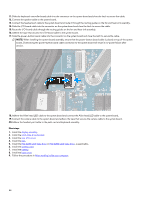
Disconnect the headset-port cable from the system board and remove it from the routing guides on the fan and heat-sink
 |
View all Dell Alienware x15 R2 manuals
Add to My Manuals
Save this manual to your list of manuals |
Page 50 highlights
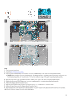
Steps 1. Peel the headset port cable from the fan and heat-sink assembly. 2. Disconnect the camera cable from the system board and peel the tape that secures the camera cable to the system board. 3. Disconnect the Alien head LED cable from the system board and peel the cable from the system board. 4. Open the latch and disconnect the power-button cable from the system board. 5. Peel the tape that secures the I/O-board cable to the system board. 6. Open the latch and disconnect the I/O-board cable from the system board and remove it from the routing guides on the fan and heat-sink assembly. 7. Disconnect the headset-port cable from the system board and remove it from the routing guides on the fan and heat-sink assembly. 8. Disconnect the speaker cable from the system board. 9. Open the latch and disconnect the keyboard-controller board cable from the system board. 10. Disconnect the power-adapter port cable from the system board. 50
-
 1
1 -
2
-
3
-
4
-
5
-
6
-
7
-
8
-
9
-
10
-
11
-
12
-
13
-
14
-
15
-
16
-
17
-
18
-
19
-
20
-
21
-
22
-
23
-
24
-
25
-
26
-
27
-
28
-
29
-
30
-
31
-
32
-
33
-
34
-
35
-
36
-
37
-
38
-
39
-
40
-
41
-
42
-
43
-
44
-
 45
45 -
 46
46 -
 47
47 -
 48
48 -
 49
49 -
 50
50 -
 51
51 -
 52
52 -
 53
53 -
 54
54 -
 55
55 -
56
-
57
-
58
-
59
-
60
-
61
-
62
-
63
-
64
-
65
-
66
-
67
-
68
-
69
-
70
-
71
-
72
-
73
-
74
-
75
 |
 |
