Dell Alienware x15 R2 Service Manual - Page 53
Steps
 |
View all Dell Alienware x15 R2 manuals
Add to My Manuals
Save this manual to your list of manuals |
Page 53 highlights
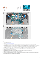
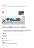
Steps 1. Turn the system board over. 2. Install the fan and heat-sink assembly. 3. Turn the system-board assembly over and place the system-board assembly on the palm-rest and keyboard assembly. NOTE: When installing the system-board assembly, align the system-board assembly to the positioning pins on the palm-rest and keyboard assembly and the extensions of the heat sink to the top edge of the palm-rest and keyboard assembly. 4. Align the screw holes on the system-board assembly with the screw holes on the palm-rest and keyboard assembly. 5. Replace the five screws (M2x4) that secure the system-board assembly to the palm-rest and keyboard assembly. 6. Adhere the display cable to the system board. 7. Slide the display cable into the connector on the system board and close the latch to secure the cable. 8. Adhere the tape that secures the display cable to the system board. 9. Align and place the power-adapter port cable and adhere the power-adapter port cable onto the fan and heat-sink assembly. 10. Connect the power-adapter port cable to the system board. 53
-
 1
1 -
2
-
3
-
4
-
5
-
6
-
7
-
8
-
9
-
10
-
11
-
12
-
13
-
14
-
15
-
16
-
17
-
18
-
19
-
20
-
21
-
22
-
23
-
24
-
25
-
26
-
27
-
28
-
29
-
30
-
31
-
32
-
33
-
34
-
35
-
36
-
37
-
38
-
39
-
40
-
41
-
42
-
43
-
44
-
45
-
46
-
47
-
 48
48 -
 49
49 -
 50
50 -
 51
51 -
 52
52 -
 53
53 -
 54
54 -
 55
55 -
 56
56 -
 57
57 -
 58
58 -
59
-
60
-
61
-
62
-
63
-
64
-
65
-
66
-
67
-
68
-
69
-
70
-
71
-
72
-
73
-
74
-
75
 |
 |
