Dell Alienware x15 R2 Service Manual - Page 54
Next steps, rear I/O-cover
 |
View all Dell Alienware x15 R2 manuals
Add to My Manuals
Save this manual to your list of manuals |
Page 54 highlights
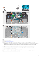
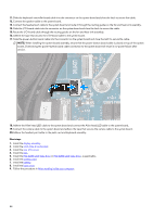
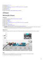
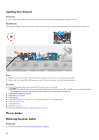
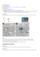
11. Slide the keyboard-controller board cable into the connector on the system board and close the latch to secure the cable. 12. Connect the speaker cable to the system board. 13. Connect the headset port cable to the system board and route it through the routing guides on the fan and heat-sink assembly. 14. Slide the I/O-board cable into the connector on the system board and close the latch to secure the cable. 15. Route the I/O-board cable through the routing guides on the fan and heat-sink assembly. 16. Adhere the tape that secures the I/O-board cable to the system board. 17. Slide the power-button board cable into the connector on the system board and close the latch to secure the cable. NOTE: When installing the system-board assembly, ensure that the power-button board cable is placed on top of the system board. Overlooking the power-button board cable connection to the system board will result in no-power failure after service. 18. Adhere the Alien head LED cable to the system board and connect the Alien head LED cable to the system board. 19. Connect the camera cable to the system board and adhere the tape that secures the camera cable to the system board. 20.Adhere the headset-port cable to the palm-rest and keyboard assembly. Next steps 1. Install the display assembly. 2. Install the solid-state drive bracket. 3. Install the rear I/O-cover. 4. Install the fans. 5. Install the M.2 2230 solid-state drive or M.2 2280 solid-state drive, as applicable. 6. Install the wireless card. 7. Install the battery. 8. Install the base cover. 9. Follow the procedure in After working inside your computer. 54
-
 1
1 -
2
-
3
-
4
-
5
-
6
-
7
-
8
-
9
-
10
-
11
-
12
-
13
-
14
-
15
-
16
-
17
-
18
-
19
-
20
-
21
-
22
-
23
-
24
-
25
-
26
-
27
-
28
-
29
-
30
-
31
-
32
-
33
-
34
-
35
-
36
-
37
-
38
-
39
-
40
-
41
-
42
-
43
-
44
-
45
-
46
-
47
-
48
-
 49
49 -
 50
50 -
 51
51 -
 52
52 -
 53
53 -
 54
54 -
 55
55 -
 56
56 -
 57
57 -
 58
58 -
 59
59 -
60
-
61
-
62
-
63
-
64
-
65
-
66
-
67
-
68
-
69
-
70
-
71
-
72
-
73
-
74
-
75
 |
 |
