Dell Alienware x15 R2 Service Manual - Page 52
Installing the system board, Prerequisites, About this task
 |
View all Dell Alienware x15 R2 manuals
Add to My Manuals
Save this manual to your list of manuals |
Page 52 highlights
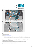
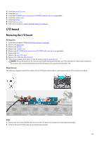
Installing the system board Prerequisites If you are replacing a component, remove the existing component before performing the installation process. About this task NOTE: When installing this component, please refer to the techsheet bundled with the service kit. This is only applicable for computers with the following Graphics Processing Unit (GPU) configurations that have Element 31 grease is applied to the CPU. ● NVIDIA GeForce RTX 3060 ● NVIDIA GeForce RTX 3070Ti ● NVIDIA GeForce RTX 3080Ti The following image indicates the connectors on your system board. 1. Display cable 3. Camera cable 5. I/O-board cable 7. Speaker cable 9. Power-adapter port cable 2. Alien head LED cable 4. Power-button cable 6. Headset port cable 8. Keyboard-controller board cable The following image(s) indicate the location of the system board and provides a visual representation of the installation procedure. 52
-
 1
1 -
2
-
3
-
4
-
5
-
6
-
7
-
8
-
9
-
10
-
11
-
12
-
13
-
14
-
15
-
16
-
17
-
18
-
19
-
20
-
21
-
22
-
23
-
24
-
25
-
26
-
27
-
28
-
29
-
30
-
31
-
32
-
33
-
34
-
35
-
36
-
37
-
38
-
39
-
40
-
41
-
42
-
43
-
44
-
45
-
46
-
 47
47 -
 48
48 -
 49
49 -
 50
50 -
 51
51 -
 52
52 -
 53
53 -
 54
54 -
 55
55 -
 56
56 -
 57
57 -
58
-
59
-
60
-
61
-
62
-
63
-
64
-
65
-
66
-
67
-
68
-
69
-
70
-
71
-
72
-
73
-
74
-
75
 |
 |
