Dell Alienware x15 R2 Service Manual - Page 48
System board, Removing the system board
 |
View all Dell Alienware x15 R2 manuals
Add to My Manuals
Save this manual to your list of manuals |
Page 48 highlights
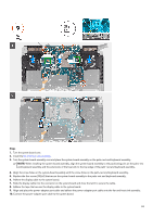
Steps 1. Using the alignment posts, place the keyboard-controller board into the slot on the palm-rest and keyboard assembly. 2. Replace the two screws (M1.6x1.6) that secure the keyboard-controller board to the palm-rest and keyboard assembly. 3. Slide the keyboard cable into the connector on the keyboard-controller board and close the latch to secure the cable. 4. Slide the touchpad cable into the connector on the keyboard-controller board and close the latch to secure the cable. 5. Slide the keyboard-controller board cable into the connector on the keyboard-controller board and close the latch to secure the cable. 6. Slide the touchpad-light cable into the connector on the keyboard-controller board and close the latch to secure the cable. NOTE: Your computer may be shipped with an touchpad-light cable depending on the configuration you have ordered. 7. Slide the keyboard-backlight cable into the connector on the keyboard-controller board and close the latch to secure the cable. 8. Align the screw holes on the keyboard-controller board bracket with the screw holes on the keyboard-controller board and palm-rest and keyboard assembly. 9. Replace the two screws (M2x1.9) that secures the keyboard-controller board bracket to the keyboard-controller board and palm-rest and keyboard assembly. 10. Adhere the tape that secures the keyboard-controller board bracket to the palm-rest and keyboard assembly. Next steps 1. Install the battery. 2. Install the base cover. 3. Follow the procedure in After working inside your computer. System board Removing the system board Prerequisites 1. Follow the procedure in Before working inside your computer. 2. Remove the base cover. 3. Remove the battery. 48
-
 1
1 -
2
-
3
-
4
-
5
-
6
-
7
-
8
-
9
-
10
-
11
-
12
-
13
-
14
-
15
-
16
-
17
-
18
-
19
-
20
-
21
-
22
-
23
-
24
-
25
-
26
-
27
-
28
-
29
-
30
-
31
-
32
-
33
-
34
-
35
-
36
-
37
-
38
-
39
-
40
-
41
-
42
-
 43
43 -
 44
44 -
 45
45 -
 46
46 -
 47
47 -
 48
48 -
 49
49 -
 50
50 -
 51
51 -
 52
52 -
 53
53 -
54
-
55
-
56
-
57
-
58
-
59
-
60
-
61
-
62
-
63
-
64
-
65
-
66
-
67
-
68
-
69
-
70
-
71
-
72
-
73
-
74
-
75
 |
 |
