Dell Latitude E5540 Dell Owners Manual
Dell Latitude E5540 Manual
 |
View all Dell Latitude E5540 manuals
Add to My Manuals
Save this manual to your list of manuals |
Dell Latitude E5540 manual content summary:
- Dell Latitude E5540 | Dell Owners Manual - Page 1
Dell Latitude E5540 Owner's Manual Regulatory Model: P44G Regulatory Type: P44G001 - Dell Latitude E5540 | Dell Owners Manual - Page 2
used in this text: Dell™, the Dell logo, Dell Boomi™, Dell Precision™ , OptiPlex™, Latitude™, PowerEdge™, PowerVault™, PowerConnect™, OpenManage™, EqualLogic™, Compellent™, KACE™, FlexAddress™, Force10™, Venue™ and Vostro™ are trademarks of Dell Inc. Intel®, Pentium®, Xeon®, Core® and Celeron® are - Dell Latitude E5540 | Dell Owners Manual - Page 3
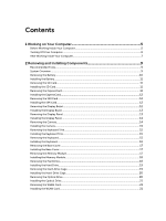
...14 Removing the Camera...14 Installing the Camera...15 Removing the Keyboard Trim...15 Installing the Keyboard Trim...15 Removing the Keyboard...15 Installing the Keyboard...16 Removing the Base Cover...17 Installing the Base Cover...17 Removing the Memory Module...17 Installing the Memory Module - Dell Latitude E5540 | Dell Owners Manual - Page 4
40 Updating the BIOS ...50 System and Setup Password...50 Assigning a System Password and Setup Password 50 Deleting or Changing an Existing System and/or Setup Password 51 4 Diagnostics...53 Enhanced Pre-Boot System Assessment (ePSA) Diagnostics 53 Device Status Lights...54 Battery Status Lights - Dell Latitude E5540 | Dell Owners Manual - Page 5
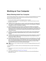
only perform troubleshooting and simple repairs as authorized in your product documentation, or as directed by the online or telephone service and support team. Damage due to servicing that is not authorized by Dell is not covered by your warranty. Read and follow the safety instructions that came - Dell Latitude E5540 | Dell Owners Manual - Page 6
computer and all attached devices from their electrical outlets. 6. Close the display and turn the computer upside-down on a flat work surface. NOTE: To avoid damaging the system board, you must remove the main battery before you service the computer. 7. Remove the main battery. 8. Turn the computer - Dell Latitude E5540 | Dell Owners Manual - Page 7
them off. After Working Inside Your Computer After you complete any replacement procedure, ensure you connect any external devices, cards, and cables before turning on your computer. CAUTION: To avoid damage to the computer, use only the battery designed for this particular Dell computer. Do not - Dell Latitude E5540 | Dell Owners Manual - Page 8
8 - Dell Latitude E5540 | Dell Owners Manual - Page 9
Installing Components This section provides detailed information on how to remove or install the components from your computer. Recommended Tools The plastic scribe System Overview Figure 1. Inside View - Back 1. coin-cell battery 2. memory modules 3. optical drive 4. WLAN card 5. hard drive 9 - Dell Latitude E5540 | Dell Owners Manual - Page 10
status-light board 4. speakers 5. ExpressCard cage 6. system fan 7. I/O board (left) 8. display assembly Removing the Battery 1. Follow the procedures in Before Working Inside Your Computer. 2. Perform the following steps: a) Slide the battery release latches into the unlock position. b) Push and - Dell Latitude E5540 | Dell Owners Manual - Page 11
Installing the Battery 1. Slide the battery into its slot until it clicks into place. 2. Follow the procedures in After Working Inside Your Computer. Removing the SD Card 1. Follow the procedures in Before Working Inside Your Computer. 2. Press in on the SD card to release it from the computer. 3. - Dell Latitude E5540 | Dell Owners Manual - Page 12
the SIM Card 1. Follow the procedures in Before Working On Your Computer. 2. Remove the battery. 3. Press and release the SIM card located on the battery wall. 4. Slide the SIM card from the computer. NOTE: The SIM slot in the computer supports only micro SIM. Installing the SIM Card 1. Insert - Dell Latitude E5540 | Dell Owners Manual - Page 13
onto the display assembly. 3. Install the battery. 4. Follow the procedures in After Working Inside Your Computer. Removing the Display Panel 1. Follow the procedures in Before Working Inside Your Computer. 2. Remove: a) battery b) display bezel 3. Remove the screws that secure the display panel - Dell Latitude E5540 | Dell Owners Manual - Page 14
Computer. Removing the Camera 1. Follow the procedures in Before Working Inside Your Computer. 2. Remove: a) battery b) display bezel 3. Perform the following steps: a) Remove the screw that secures the camera and microphone module. b) Disconnect the camera cable. c) Lift and remove the camera and - Dell Latitude E5540 | Dell Owners Manual - Page 15
screw to secure the camera and microphone module. 4. Install: a) display bezel b) battery 5. Follow the procedures in After Working Inside Your Computer. Removing the Keyboard Trim 1. Follow the procedures in Before Working Inside Your Computer. 2. Remove the battery. 3. Perform the following steps - Dell Latitude E5540 | Dell Owners Manual - Page 16
and right side ensuring that all the snaps are fully engaged with the computer. 4. Install the screws to secure the keyboard to the palmrest. 5. Install the screws at the back of the computer. 6. Install: a) keyboard trim b) battery 7. Follow the procedures in After Working Inside Your Computer. 16 - Dell Latitude E5540 | Dell Owners Manual - Page 17
screws that secure the base cover to the computer. 3. Install the battery. 4. Follow the procedures in After Working Inside Your Computer. Removing the Memory Module 1. Follow the procedures in Before Working Inside Your Computer. 2. Remove: a) battery b) base cover 3. Pry the retention clips away - Dell Latitude E5540 | Dell Owners Manual - Page 18
to secure the memory module to the system board. 3. Install: a) base cover b) battery 4. Follow the procedures in After Working Inside Your Computer. Removing the Hard Drive 1. Follow the procedures in Before Working Inside Your Computer. 2. Remove: a) battery b) base cover 3. Perform the following - Dell Latitude E5540 | Dell Owners Manual - Page 19
drive on its connector. 3. Install: a) base cover b) battery 4. Follow the procedures in After Working Inside Your Computer. Removing the Hard-Drive Cage 1. Follow the procedures in Before Working Inside Your Computer. 2. Remove: a) battery b) base cover c) hard drive 3. Perform the following steps - Dell Latitude E5540 | Dell Owners Manual - Page 20
a) hard drive b) base cover c) battery 4. Follow the procedures in After Working Inside Your Computer. Removing the Optical Drive 1. Follow the procedures in Before Working Inside Your Computer. 2. Remove: a) battery b) base cover 3. Perform the following steps: a) Remove the screw that secures the - Dell Latitude E5540 | Dell Owners Manual - Page 21
drive in its place. 6. Install: a) base cover b) battery 7. Follow the procedures in After Working Inside Your Computer. Removing the WLAN Card 1. Follow the procedures in Before Working Inside Your Computer. 2. Remove: a) battery b) base cover 3. Perform the following steps: a) Disconnect the - Dell Latitude E5540 | Dell Owners Manual - Page 22
4. Follow the procedures in After Working Inside Your Computer. Removing the Display Hinge 1. Follow the procedures in Before Working Inside Your Computer. 2. Remove: a) battery b) base cover c) keyboard trim d) keyboard 3. Perform the following steps: a) Remove the screws that secure the display - Dell Latitude E5540 | Dell Owners Manual - Page 23
keyboard b) keyboard trim c) base cover d) battery 4. Follow the procedures in After Working Inside Your Computer. Removing the Palmrest 1. Follow the procedures in Before Working Inside Your Computer. 2. Remove: a) SD card b) battery c) base cover d) keyboard trim e) keyboard f) memory g) optical - Dell Latitude E5540 | Dell Owners Manual - Page 24
: a) power-button cable b) fingerprint-scanner cable c) touch-pad cable d) media button cable 3. Tighten the screws to secure the palmrest at the front and back of the computer. 4. Install: a) display hinge b) hard-drive cage c) hard drive d) optical drive e) memory f) keyboard g) keyboard trim 24 - Dell Latitude E5540 | Dell Owners Manual - Page 25
j) SD card 5. Follow the procedures in After Working Inside Your Computer. Removing the ExpressCard Cage 1. Follow the procedures in Before Working Inside Your Computer. 2. Remove: a) SD card b) battery c) base cover d) keyboard trim e) keyboard f) display hinge g) palmrest 3. Perform the following - Dell Latitude E5540 | Dell Owners Manual - Page 26
g) SD card 4. Follow the procedures in After Working Inside Your Computer. Removing the System Fan 1. Follow the procedures in Before Working Inside Your Computer. 2. Remove: a) SD card b) battery c) base cover d) keyboard trim e) keyboard f) memory g) optical drive h) hard drive i) hard-drive cage - Dell Latitude E5540 | Dell Owners Manual - Page 27
SD card 6. Follow the procedures in After Working Inside Your Computer. Removing the System Board 1. Follow the procedures in Before Working Inside Your Computer. 2. Remove: a) SD card b) battery c) base cover d) keyboard trim e) keyboard f) memory g) optical drive h) hard drive i) hard-drive cage - Dell Latitude E5540 | Dell Owners Manual - Page 28
the screws that secure the system board on the computer. b) Lift and remove the system board from the computer. Installing the System Board 1. Align the system board into its original position on the computer. 2. Replace and tighten the screws to secure the system board to the computer. 3. Connect - Dell Latitude E5540 | Dell Owners Manual - Page 29
memory j) keyboard k) keyboard trim l) base cover m) battery n) SD card 6. Follow the procedures in After Working Inside Your Computer. Removing the Heatsink 1. Follow the procedures in Before Working Inside Your Computer. 2. Remove: a) SD card b) battery c) base cover d) keyboard trim e) keyboard - Dell Latitude E5540 | Dell Owners Manual - Page 30
i) optical drive j) memory k) keyboard l) keyboard trim m) base cover n) battery o) SD card 4. Follow the procedures in After Working Inside Your Computer. Removing the I/O Board (Left) 1. Follow the procedures in Before Working Inside Your Computer. 2. Remove: a) SD card b) battery c) base cover 30 - Dell Latitude E5540 | Dell Owners Manual - Page 31
keyboard trim e) keyboard f) memory g) optical drive h) hard drive i) hard-drive cage j) WLAN card k) display hinge l) palmrest m) system fan n) ExpressCard cage o) system board 3. Perform the following steps: a) Remove optical drive j) memory k) keyboard l) keyboard trim m) base cover n) battery 31 - Dell Latitude E5540 | Dell Owners Manual - Page 32
SD card 4. Follow the procedures in After Working Inside Your Computer. Removing the I/O Board (Right) 1. Follow the procedures in Before Working Inside Your Computer. 2. Remove: a) SD card b) battery c) base cover d) keyboard trim e) keyboard f) memory g) optical drive h) hard drive i) hard-drive - Dell Latitude E5540 | Dell Owners Manual - Page 33
trim m) base cover n) battery o) SD card 4. Follow the procedures in After Working Inside Your Computer. Removing the Power Connector 1. Follow the procedures in Before Working Inside Your Computer. 2. Remove: a) SD card b) battery c) base cover d) keyboard trim e) keyboard f) memory g) hard drive - Dell Latitude E5540 | Dell Owners Manual - Page 34
o) SD card 4. Follow the procedures in After Working Inside Your Computer. Removing the Speakers 1. Follow the procedures in Before Working Inside Your Computer. 2. Remove: a) SD memory card b) battery c) base cover d) keyboard trim e) keyboard f) memory g) optical drive h) hard drive i) hard-drive - Dell Latitude E5540 | Dell Owners Manual - Page 35
j) memory k) keyboard l) keyboard trim m) base cover n) battery o) SD card 5. Follow the procedures in After Working Inside Your Computer. Removing the Status-Light Board 1. Follow the procedures in Before Working Inside Your Computer. 2. Remove: a) SD card b) battery c) base cover d) keyboard trim - Dell Latitude E5540 | Dell Owners Manual - Page 36
k) display hinge l) palmrest m) system fan n) ExpressCard cage o) system board p) speakers 3. Perform the following steps: a) Remove the screw that secures the LED cover. b) Un-route the status-light board cable from its channels. c) Remove the screw that secures the status-light board and lift to - Dell Latitude E5540 | Dell Owners Manual - Page 37
a) speakers b) system board c) system fan d) ExpressCard cage e) palmrest f) display hinge g) WLAN card h) hard-drive cage i) hard drive j) optical drive k) memory l) keyboard m) keyboard trim n) base cover o) battery p) SD card 6. Follow the procedures in After Working Inside Your Computer. 37 - Dell Latitude E5540 | Dell Owners Manual - Page 38
38 - Dell Latitude E5540 | Dell Owners Manual - Page 39
, you can: • Change the NVRAM settings after you add or remove hardware • View the system hardware configuration • Enable or disable integrated devices • Set performance and power management thresholds • Manage your computer security Boot Sequence Boot Sequence allows you to bypass the System Setup - Dell Latitude E5540 | Dell Owners Manual - Page 40
Hard Drive, MiniCard Device, ODD Device, Dock eSATA Device, LOM MAC Address, Video Controller, Video BIOS Version, Video Memory, Panel Type, Native Resolution, Audio Controller, Wi-Fi Device, WiGig Device, Cellular Device, Bluetooth Device. Battery Information Displays the battery status and the - Dell Latitude E5540 | Dell Owners Manual - Page 41
configure the parallel port on the docking station. The options are: • Disabled • AT: This option is enabled by default. • PS2 • ECP Allows you to configure the integrated serial port. The options are: • Disabled • COM1: This option is enabled by default. • COM2 • COM3 • COM4 SATA Operation Allows - Dell Latitude E5540 | Dell Owners Manual - Page 42
cannot see any device attached to this port. • Enable Boot Support • Enable External USB Port • Enable USB3.0 Controller NOTE: USB keyboard and mouse always work in the BIOS setup irrespective of these settings. This field enables or disables the integrated audio controller. By default, the Enable - Dell Latitude E5540 | Dell Owners Manual - Page 43
Option Description NOTE: All devices are enabled by default. You can also enable or disable Media Card. Table 4. Video Option LCD Brightness Description Allows you to set the display brightness depending up on the power source (On Battery and On AC). NOTE: The Video setting will only be visible - Dell Latitude E5540 | Dell Owners Manual - Page 44
activate or disable the feature and no further changes will be allowed Deactivate (default) Allows you to enable the Execute Disable mode of the processor. Enable CPU XD Support (default) Allows you to set an option to enter the Option ROM Configuration screens using hotkeys during boot. The options - Dell Latitude E5540 | Dell Owners Manual - Page 45
of some applications will improve with the additional cores. This option is enabled by default.Allows you to enable or disable multi-core support for the processor. The options are: • All •1 •2 Default Setting: All Allows you to enable or disable the Intel SpeedStep feature. Default Setting: Enable - Dell Latitude E5540 | Dell Owners Manual - Page 46
Standby, the system setup will remove power from all of the USB ports to conserve battery power. • Enable USB Wake Support • DEnable USB Wake Support is not selected Allows you to enable or disable the feature that automatically switches from wired or wireless networks without depending on the - Dell Latitude E5540 | Dell Owners Manual - Page 47
to enable the keypad that is embedded in the internal keyboard. • Fn Key Only: This option is enabled by default. • By Numlock NOTE: The Keyboard (Embedded) option is not supported in Latitude E5540 Allows you to define how the system handles mouse and touch pad input. The options are: • Serial - Dell Latitude E5540 | Dell Owners Manual - Page 48
Fastboot Extended BIOS POST Time Description • Toushpad/PS-2 Mouse: This option is enabled by default. Allows you to enable the Numlock option when the computer boots. Enable Network (default) Allows you to set the option where the key is used to simulate the key feature. Enable - Dell Latitude E5540 | Dell Owners Manual - Page 49
Option Service Tag Asset Tag Table 13. System Logs Option BIOS Events Thermal Events Power Events Description Allows to set the wireless devices that can be controlled by the wireless switch. The options are: • WWAN • WLAN • WiGig • Bluetooth All the options are enabled by default. • WLAN - Dell Latitude E5540 | Dell Owners Manual - Page 50
to update your BIOS (system setup), on replacing the system board or if an update is available. For laptops, ensure that your computer battery is fully charged and connected to a power outlet 1. Re-start the computer. 2. Go to dell.com/support. 3. Enter the Service Tag or Express Service Code and - Dell Latitude E5540 | Dell Owners Manual - Page 51
NOTE: If the password jumper is disabled, the existing System Password and Setup Password is deleted and you need not provide the system password to log on to the computer. To enter a system setup, press immediately after a power-on or re-boot. 1. In the System BIOS or System Setup screen, - Dell Latitude E5540 | Dell Owners Manual - Page 52
52 - Dell Latitude E5540 | Dell Owners Manual - Page 53
yourself, service and support personnel can use the diagnostics results to help you solve the problem. Enhanced Pre-Boot System Assessment (ePSA) Diagnostics The ePSA diagnostics (also known as system diagnostics) performs a complete check of your hardware. The ePSA is embedded with the BIOS and is - Dell Latitude E5540 | Dell Owners Manual - Page 54
or unsupported non-Dell AC adapter is attached to your laptop. Alternately blinking amber light with steady white light Constantly blinking amber light Temporary battery failure with AC adapter present. Fatal battery failure with AC adapter present. Light off Battery in full charge mode with AC - Dell Latitude E5540 | Dell Owners Manual - Page 55
• Intel Core i3 series • Intel Core i5 series • Intel Core i7 series up to 8 MB Table 16. Memory Feature Memory connector Memory capacity Memory type Minimum memory Maximum memory Specification two SoDIMM slots 2 GB, 4 GB, or 8 GB DDR3 SDRAM 1600 Mhz 2 GB 8 GB Table 17. mSATA Support Feature - Dell Latitude E5540 | Dell Owners Manual - Page 56
Type Controller UMA Discrete Table 20. Communications Feature Network adapter Wireless Table 21. Ports and Connectors Feature Audio (optional) Video Specification • Supports mSATA and WWAN on Latitude E5440 • Supports mSATA on Latitude E5540. Specification four-channel high definition audio Realtek - Dell Latitude E5540 | Dell Owners Manual - Page 57
3.0 Memory card reader Docking port Subscriber Identity Module (SIM) port Table 22. Display Feature Type Latitude E5440 Latitude E5540 Size Latitude E5440 Latitude E5540 Dimensions: Latitude E5440: Height Width Diagonal Active ares (X/Y) Maximum resolution Maximum Brightness Latitude E5540: Height - Dell Latitude E5540 | Dell Owners Manual - Page 58
angle Refresh rate Minimum Viewing angles: Horizontal Vertical Pixel pitch: Latitude E5440 Latitude E5540 Table 23. Keyboard Feature Number of keys Layout Table 24. Touchpad Feature Active Area: X-axis Y-axis Table 25. Battery Feature Type Dimensions: 58 Specification 360 mm (14.17 inches) 394.24 - Dell Latitude E5540 | Dell Owners Manual - Page 59
. 3 V CR2032 lithium coin cell Table 26. AC Adapter Feature Type Input voltage Input current (maximum) Input frequency Output power Output current Latitude E5440 65 W 100 VAC to 240 VAC 1.7 A 50 Hz to 60 Hz 65 W 3.34 A (continuous) Latitude E5540 90 W adapter 100 VAC to 240 VAC 1.5 A 50 - Dell Latitude E5540 | Dell Owners Manual - Page 60
Feature Rated output voltage Temperature range: Operating Non-Operating Latitude E5440 19.5 +/- 1.0 VDC Latitude E5540 19.5 +/- 1.0 VDC 0 °C to 40 °C (32 °F to .00 mm (9.25 inches) Weight (minimu m) 1.99 kg (4.40 lb) Latitude E5540 Touch Non-touch Front - 28.25 mm (1.11 inches) Back - 33.60 - Dell Latitude E5540 | Dell Owners Manual - Page 61
options. Availability varies by country and product, and some services may not be available in your area. To contact Dell for sales, technical support, or customer service issues: 1. Visit dell.com/support 2. Select your support category. 3. Verify your country or region in the Choose a Country
-
 1
1 -
 2
2 -
 3
3 -
 4
4 -
 5
5 -
 6
6 -
 7
7 -
8
-
9
-
10
-
11
-
12
-
13
-
14
-
15
-
16
-
17
-
18
-
19
-
20
-
21
-
22
-
23
-
24
-
25
-
26
-
27
-
28
-
29
-
30
-
31
-
32
-
33
-
34
-
35
-
36
-
37
-
38
-
39
-
40
-
41
-
42
-
43
-
44
-
45
-
46
-
47
-
48
-
49
-
50
-
51
-
52
-
53
-
54
-
55
-
56
-
57
-
58
-
59
-
60
-
61
 |
 |

Dell Latitude E5540
Owner's Manual
Regulatory Model: P44G
Regulatory Type: P44G001