Dell Latitude E5540 Dell Owners Manual - Page 33
Removing the Power Connector
 |
View all Dell Latitude E5540 manuals
Add to My Manuals
Save this manual to your list of manuals |
Page 33 highlights
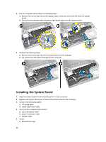
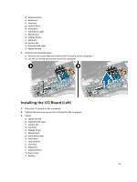
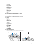
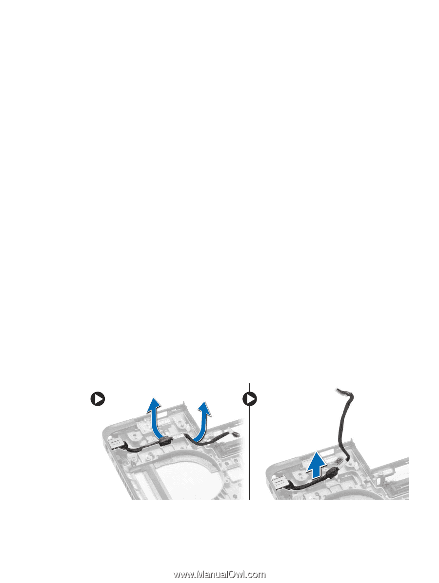
d) palmrest e) display hinge f) WLAN card g) hard drive h) hard-drive cage i) optical drive j) memory k) keyboard l) keyboard trim m) base cover n) battery o) SD card 4. Follow the procedures in After Working Inside Your Computer. Removing the Power Connector 1. Follow the procedures in Before Working Inside Your Computer. 2. Remove: a) SD card b) battery c) base cover d) keyboard trim e) keyboard f) memory g) hard drive h) hard-drive cage i) optical drive j) WLAN card k) display hinge l) palmrest m) ExpressCard cage n) system fan o) system board 3. Perform the following steps: a) Remove the power-connector cable from the routing channels. b) Lift and remove the power connector from the computer. 33
-
 1
1 -
2
-
3
-
4
-
5
-
6
-
7
-
8
-
9
-
10
-
11
-
12
-
13
-
14
-
15
-
16
-
17
-
18
-
19
-
20
-
21
-
22
-
23
-
24
-
25
-
26
-
27
-
 28
28 -
 29
29 -
 30
30 -
 31
31 -
 32
32 -
 33
33 -
 34
34 -
 35
35 -
 36
36 -
 37
37 -
 38
38 -
39
-
40
-
41
-
42
-
43
-
44
-
45
-
46
-
47
-
48
-
49
-
50
-
51
-
52
-
53
-
54
-
55
-
56
-
57
-
58
-
59
-
60
-
61
 |
 |
d)
palmrest
e)
display hinge
f)
WLAN card
g)
hard drive
h)
hard-drive cage
i)
optical drive
j)
memory
k)
keyboard
l)
keyboard trim
m)
base cover
n)
battery
o)
SD card
4.
Follow the procedures in
After Working Inside Your Computer
.
Removing the Power Connector
1.
Follow the procedures in
Before Working Inside Your Computer
.
2.
Remove:
a)
SD card
b)
battery
c)
base cover
d)
keyboard trim
e)
keyboard
f)
memory
g)
hard drive
h)
hard-drive cage
i)
optical drive
j)
WLAN card
k)
display hinge
l)
palmrest
m)
ExpressCard cage
n)
system fan
o)
system board
3.
Perform the following steps:
a)
Remove the power-connector cable from the routing channels.
b)
Lift and remove the power connector from the computer.
33