Epson TM U295 Operation Guide
Epson TM U295 - B/W Dot-matrix Printer Manual
 |
View all Epson TM U295 manuals
Add to My Manuals
Save this manual to your list of manuals |
Epson TM U295 manual content summary:
- Epson TM U295 | Operation Guide - Page 1
TM-U295/U295P Operator's Manual Using this online operator's guide The words on the left side of this screen are bookmarks for all the topics in this guide. Use the scroll bar next to the bookmarks to find any topic you want. Click a bookmark to instantly jump to its topic. (If you wish, - Epson TM U295 | Operation Guide - Page 2
TM-U295/U295P Operator's Manual 400483605 - Epson TM U295 | Operation Guide - Page 3
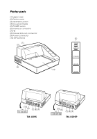
Printer parts (1) Upper case (2) Printer cover (3) Operation panel (4) Document table (5) POWER switch (6) Interface connector (7) FG (8) Drawer kick-out connector (9) Power connector (10) DIP switches (3) (1) (2) (5) (4) (10) (6) (7) (8) (9) TM-U295 (10) (6) (7) (8) (9) TM-U295P - Epson TM U295 | Operation Guide - Page 4
alterations to this product, or (excluding the U.S.) failure to strictly comply with Seiko Epson Corporation's operating and maintenance instructions. Seiko Epson Corporation shall not be liable against any damages or problems arising from the use of any options or any consumable products other than - Epson TM U295 | Operation Guide - Page 5
and, if not installed and used in accordance with the instruction manual, may cause harmful interference to radio communications. Operation of his own expense. WARNING The connection of a non-shielded printer interface cable to this printer will invalidate the FCC Verification of this device and may - Epson TM U295 | Operation Guide - Page 6
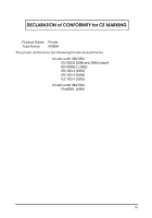
DECLARATION of CONFORMITY for CE MARKING Product Name: Printer Type Name: M66SA The printer conforms to the following Directives and Norms Directive 89/336/EEC EN 55022 (1986 and 1994) class B EN 50082-1 (1992) IEC 801-2 (1991) IEC 801-3 ( - Epson TM U295 | Operation Guide - Page 7
DECLARATION of CONFORMITY for CE MARKING Product Name: Type Name: Printer M117A The printer conforms to the following Directives and Norms Directive 89/336/EEC EN 55022 (1986 and 1994) class B EN 50082-1 (1992) IEC 801-2 (1991) IEC 801-3 ( - Epson TM U295 | Operation Guide - Page 8
TM-U295 and TM-U295P are terminal slip printers which use a 7-pin shuttle dot printing method, and provide the different modes, standard and page*. The main features of the TM-U295 and TM-U295P printers be sure to read the instructions in this manual carefully before using your new EPSON printer. v - Epson TM U295 | Operation Guide - Page 9
Setting Up and Using t Chapter 1 contains information on setting the printer up and setting the DIP switches. t Chapter 2 contains information on using the printer. t Chapter 3 contains troubleshooting information. Reference t Chapter 4 contains specifications Notes, Cautions, and Warnings Note - Epson TM U295 | Operation Guide - Page 10
the Power Supply 1-8 Installing the Ribbon 1-9 Inserting Paper 1-12 Running the Self Test 1-13 Setting the DIP Switches 1-14 TM-U295 1-16 TM-U295P 1-17 Chapter 2 Using the Printer Buttons 2-1 Indicator Lights 2-1 Replacing a Used Ribbon 2-2 Chapter 3 Troubleshooting Power problems - Epson TM U295 | Operation Guide - Page 11
Chapter 5 Commands Command Notation 5-1 Control Commands 5-2 viii - Epson TM U295 | Operation Guide - Page 12
Chapter 1 Installation Unpacking When you unpack the TM-U295 or TM-U295P printer, make sure you have these items. If any item is missing or damaged, please contact your dealer for assistance. Damper Ribbon cassette Hexagonal lock screws (2 pcs) (only for the TM-U295) Note: See the Note on page - Epson TM U295 | Operation Guide - Page 13
these steps: turn on the printer, press the RELEASE button, press the FORWARD button, turn off the printer, and put the transportation damper back where it was when you received the printer. Connecting the Printer to the Computer You need an appropriate interface cable to connect your computer to - Epson TM U295 | Operation Guide - Page 14
TM-U295 You need an appropriate serial interface cable to connect your computer to the printer. 1. Make sure that the printer and the computer are turned off. Then plug the cable into the connector on the back of the printer, as shown. Note: Your printer comes with inch-type hexagonal lock screws - Epson TM U295 | Operation Guide - Page 15
to the connector on your computer. TM-U295P You need an appropriate parallel interface cable to connect your computer to the printer. 1. Make sure that the printer and the computer are turned off. Then plug the cable into the connector on the back of the printer, as shown. Note: Squeeze the wire - Epson TM U295 | Operation Guide - Page 16
Connecting the Printer to the Drawer Plug the drawer cable into the drawer kick-out connector on the back of the printer next to the computer interface connector. TM-U295 TM-U295P CAUTION: Do not connect a telephone line to the drawer kick out connector. Installation 1-5 - Epson TM U295 | Operation Guide - Page 17
Den Drucker an die Lade anschließen Das Kabel der Lade an die Schnappsteckerbuchse (neben der Schnittstellenbuchse) an der Hinterseite des Druckers anschließen. TM-U295 TM-U295P CAUTION: Kein Telefonkabel an die Schnappsteckerbuchse anschließen. 1-6 Installation - Epson TM U295 | Operation Guide - Page 18
your printer. Recommended wire is described below. Thickness of wire: AWG 18 or equivalent Diameter of terminal to be attached: 3.2 1. Make sure that the printer is turned off. 2. Connect the ground wire to the printer using the FG screw on the back of the printer, as shown. TM-U295 TM-U295P - Epson TM U295 | Operation Guide - Page 19
. CAUTION: Using an incorrect power supply can cause serious damage to the printer. 1. Make sure that the power supply is turned off. 2. Plug the power supply's cable into the printer's connector as shown below. Note that the flat side of the connector faces up. TM-U295 TM-U295P 1-8 Installation - Epson TM U295 | Operation Guide - Page 20
cord into an outlet. Installing the Ribbon Be sure to use a ribbon cassette that meets the printer's specifications. The EPSON ERC-27 is recommended. Note: For instructions on replacing a used ribbon, see Chapter 2. 1. Turn the printer on using the power switch on its left side. 2. Press the RELEASE - Epson TM U295 | Operation Guide - Page 21
CAUTION: Be sure to perform the steps above because it is necessary to make sure that the printer is in the paper release mode before you install the ribbon cassette. 4. Open the printer cover by slightly pressing the ridges on the top left and pulling the cover forward, as shown in the illustration - Epson TM U295 | Operation Guide - Page 22
6. Carefully insert the ribbon cassette in the printer as shown in the illustration below. Notice exactly where the ribbon must go. 7. Then push firmly on the right side and then the left side of the ribbon cartridge until each side clicks into place. Installation 1-11 - Epson TM U295 | Operation Guide - Page 23
and specifications on the paper you can use, see Chapter 4. To insert paper, follow these steps: 1. Make sure that a ribbon cassette is installed in the printer. 2. Turn on the printer. The POWER light comes on. 3. Press the RELEASE button. The RELEASE light comes on, which indicates that the - Epson TM U295 | Operation Guide - Page 24
independent of any other equipment or software. The self test checks the control circuits, printer mechanisms, print quality, RAM, ROM version, and DIP switch settings. To perform the self test, follow the steps below: 1. Insert a sheet of paper following the instructions on page 1-12. 2. Turn off - Epson TM U295 | Operation Guide - Page 25
second part of the test. After the printer prints a pattern, it prints the following message: ***completed*** The printer ejects the paper; then enters the normal mode. Setting the DIP Switches You can change several interface settings by changing the DIP switch settings. If you need to change any - Epson TM U295 | Operation Guide - Page 26
2. Turn the printer over and locate the DIP switches, as shown below. 3. Notice that ON is marked on the set of switches. Use tweezers or another narrow tool to move the switches. 4. Use the following tables to set the DIP switches. Installation 1-15 - Epson TM U295 | Operation Guide - Page 27
TM-U295 Switch 1 2 3 4 5 6 7 8 9 10 Function Data reception error Receive buffer capacity Handshaking Word length Parity check Parity selection ON Ignored 35 bytes XON/XOFF 7 bits Yes Even See - Epson TM U295 | Operation Guide - Page 28
TM-U295P Switch 1 2 3 4 5 6 7 8 9 10 Function ON Auto-line feed Normally enabled Receive buffer capacity 35 bytes Undefined Undefined Undefined Undefined Undefined Undefined Undefined Reserved. Setting must not be changed OFF Normally disabled 512 bytes Note: If you change any DIP - Epson TM U295 | Operation Guide - Page 29
Chapter 2 Using the Printer The control panel has three buttons and three lights. Buttons All three of these buttons can be You can also use the RELEASE button to start a self test. See Chapter 1 for details. Indicator Lights POWER This light is on whenever power is supplied to the printer. Using the - Epson TM U295 | Operation Guide - Page 30
t Home position error t Timing error t Drive circuit error t Power supply voltage error If this light blinks, turn off the printer, make sure that no paper is jammed in it, and then turn it back on. If the light is still blinking, contact a qualified service person. PAPER OUT This light is on when - Epson TM U295 | Operation Guide - Page 31
Then remove the used ribbon by grasping the handle and pulling straight out, as shown by the arrow in the illustration below. Then follow the rest of the steps in "Installing the Ribbon" in Chapter 1. Using the Printer 2-3 - Epson TM U295 | Operation Guide - Page 32
3 Troubleshooting This chapter gives the solutions to some printer problems. Power problems The POWER light does not come on. Make sure that the power supply cables are correctly plugged into the printer, the power unit, and to the power outlet. Make sure that power is supplied to the power outlet - Epson TM U295 | Operation Guide - Page 33
Chapter 4 Reference Information Printing Specifications Printing Method: Impact dot matrix Head Wires 7-pin shuttle type Printing Direction: Unidirectional Lines per second Characters per line 5 x 7 font: 1.9 to 2.3 7 x 7 font: 1.9 to 2.3 5 x 7 font: 35 7 x 7 font : 42 Characters per inch: - Epson TM U295 | Operation Guide - Page 34
Character structure: Character size: 5 x 7 with 1-dot spacing (normal dot) 7 x 7 with 3-dot spacing (half dot) 5 x 7 font: ANK: 1.6 mm (.063") x 2.9 mm (.114") Graphics: 1.9 mm (.075") x 2.9 mm (.114") 7 x 7 font: ANK: 1.3 mm (.051") x 2.9 mm (.114") Graphics: 1.6 mm (.063") x 2.9 mm (.114") 4-2 - Epson TM U295 | Operation Guide - Page 35
Paper Specifications Paper type: Total thickness: Paper size: Copy capability and paper thickness: Normal (high quality), pressure sensitive, and carbon copy papers Single-play paper: 0.09 to 0.25 mm (.0035 to .0098") Copy paper: 0.09 to 0.35 mm (.0035 to .0138") 80 mm (W) × 69 mm (L) to 182 mm - Epson TM U295 | Operation Guide - Page 36
(print mode) Original + 1 to 2 copies 5° to 40°C (41° to 104°F) Notes on slip paper t Slip paper should be flat, without curls, wrinkles, or camber, especially at the paper edges. Otherwise, the paper may become ink stained. t When using multiply-ply carbon copy paper, it should be flat and the - Epson TM U295 | Operation Guide - Page 37
stopper is adjustable in the range 26.5 to 36.5 mm (1.04 to 1.44"). 2. The TOF and BOF sensors are fixed and cannot be adjusted. 3. After slip paper is set at the mechanical form stopper, the top margin can be shortened up to 21.2 mm (.83") by feeding the paper backwards (ejection - Epson TM U295 | Operation Guide - Page 38
Electrical Specifications Supply voltage: Current consumption: +24 VDC ± 10% Operating (except for drawer kickout): Mean - approx. 600 mA at 24 VDC (full-column printing and data transmission of - Epson TM U295 | Operation Guide - Page 39
EMI and Safety Standards EMI standards (measured when using the printer with the Epson PS-150): Safety standards: FCC: CE marking: Class A UL1950-2TH-D3 (Recognized component) CSA950-D3 (Recognized component) EN60950 (IEC950 2TH) Reliability Life: MTBF: MCBF: 3,000, - Epson TM U295 | Operation Guide - Page 40
ribbon and paper) Interface Specifications Serial interface: RS-232 compatible Parallel interface: IEEE 1284 compatible (Nibble/Byte Modes) Note: The interface is a factory installed option. One of the interfaces (serial or parallel) is already installed. Note: Refer to the EPSON TM-U295/U295P - Epson TM U295 | Operation Guide - Page 41
ranges for the arguments. [Description] Describes the function of the command. [Notes] Provides important information on setting and using the printer command, if necessary. [Default] Gives the default values, if any, for the command parameters. [Reference] Lists related commands. [Example - Epson TM U295 | Operation Guide - Page 42
and return to standard mode (in page mode) [Format] ASCII FF Hex 0C Decimal 12 This command functions differently depending on the printer mode selected. ŒWhen standard mode is selected: [Description] Prints the data in print buffer and ejects the sheet. [Notes] [Reference] • When the - Epson TM U295 | Operation Guide - Page 43
Transmit error status n = 5: Transmit slip paper status [Notes] • The printer executes this command upon receiving it. • When transmitting status, the printer transmits only 1 byte without confirming the condition of the DSR signal. • With the serial interface model, this command is executed even - Epson TM U295 | Operation Guide - Page 44
status transmitted by the DLE EOT command and the ASB status must be differentiated. • If the n is out of the specified range, the printer ignores this command. n = 1: Printer status Bit Off/On Hex Decimal Function 0 Off 00 0 Not used. Fixed to Off. 1 On 02 2 Not used. Fixed to On. Off 2 On - Epson TM U295 | Operation Guide - Page 45
Bit Off/On Hex Decimal Function Off 3 On 00 0 08 8 Paper is not being fed by using the paper feed button. Paper is being fed by the paper feed button. 4 On 10 16 Not used. Fixed to On. Off 5 On 00 0 20 32 No paper-end stop. Printing stops due to paper end. Off 6 On 00 0 40 64 No error. - Epson TM U295 | Operation Guide - Page 46
the TOF sensor. 7 Off 00 0 Not used. Fixed to Off. Bit 3: Bit 5 and 6: [Reference] Becomes Off (not waiting) just before actual slip selection takes place after slip paper is detected Transmits the current status of the TOF and BOF sensors. ESC u, ESC v, GS a CAN [Name] Cancel print data in - Epson TM U295 | Operation Guide - Page 47
[Description] Sets the character spacing for the right side of the character. [Notes] • The right-side character spacing for double-width mode is twice the normal value. • The character spacing is set in increment of half dot. • In page mode, the actual dot positions shift by half dot. • This - Epson TM U295 | Operation Guide - Page 48
[Notes] [Default] • The printer can underline all characters (including the right-side character spacing), but cannot underline the space set by an HT. • When both double-height and double- - Epson TM U295 | Operation Guide - Page 49
define multiple characters for consecutive character codes. • After user-defined characters are defined, they are available until another definition is made; ESC @ is executed; the printer is reset; or the power is turned off. • If the values of y, c1, c2, or x are out of the specified range, the - Epson TM U295 | Operation Guide - Page 50
•7 × 7 font when the dot pattern for code 32 (20H) is defined as shown below: p1 p2 p3 p4 p5 p6 p7 p8 p9 p10 MSB LSB ASCII code ESC & y c1 c2 x p1 p2 p3 p4 p5 p6 p7 Hex code 1B 25 01 20 20 07 1E 20 48 80 48 20 1E 5-10 Commands - Epson TM U295 | Operation Guide - Page 51
the values of m and nH are out of the specified range, the following data is processed as normal data. • After printing a bit image, the printer returns to normal data processing mode. • In page mode, double density bit image data is not available. • The relationship between the image data and the - Epson TM U295 | Operation Guide - Page 52
• The relationship between the image data and the dots to be printed is as follows: 76 54 32 1 0 Print data Top Bottom Bit image data ESC 2 [Name] Select 1/6-inch line spacing [Format] ASCII ESC 2 Hex 1B 32 Decimal 27 50 [Description] Selects 1/6-inch line spacing. [Note] The line - Epson TM U295 | Operation Guide - Page 53
, it may go off-line due to printer operation. n = 1 ESC @ [Name] Initialize printer [Format] ASCII ESC @ Hex 1B 40 Decimal 27 64 [Description] Clears the data in the print buffer and resets the printer mode to the mode that was in effect when the power was turned on. Commands 5-13 - Epson TM U295 | Operation Guide - Page 54
[Notes] • The DIP switch settings are not checked again. • The data in the receive buffer is not cleared. • The macro definition is not cleared. ESC C n [Name] Set cut sheet - Epson TM U295 | Operation Guide - Page 55
[Notes] [Default] • Up to 32 tab positions (k = 32) can be set. Data exceeding 32 tab positions is processed as normal data. • When [n]k is less than or equal to the preceding value [n]k-1, tab setting is finished and the following data is processed as normal data. • When [n]k exceeds the number of - Epson TM U295 | Operation Guide - Page 56
page mode [Format] ASCII ESC L Hex 1B 4C Decimal 27 76 [Description] Switches from standard mode to page mode. [Notes] • This command is enabled only the printable area defined by ESC W. • In page mode, the printer buffer receives data in the printable area specified by ESC W and prints - Epson TM U295 | Operation Guide - Page 57
7 × 7 font and underline mode specification and cancel: ESC ! • This command is effective only in standard mode. • ESC @ command returns the printer to standard mode without printing any data. Standard mode FF ESC R n [Name] Select an international character set [Format] ASCII ESC R n Hex 1B - Epson TM U295 | Operation Guide - Page 58
ESC T n [Name] Select print direction in page mode [Format] ASCII ESC T n Hex 1B 54 n Decimal 27 84 n [Range] 0 ≤ n ≤ 3 48 ≤ n ≤ 51 [Description] Selects the print direction and starting position in page mode. n specifies the print direction and starting position as follows: n - Epson TM U295 | Operation Guide - Page 59
dx = [dxL + dxH ! 256] dy = [dyL + dyH ! 256] The printable area is set as shown in the figure below. (0, 0) Printable area of the paper (x0, y0) dx dy Printing area (x0+dx-1, y0+dy-1) (209 dots, 479 dots) [Notes] [Default] [Reference] • The maximum printable area in the horizontal direction - Epson TM U295 | Operation Guide - Page 60
detects a paper-end, the paper end signal is output. • This command is available only with a parallel interface and is ignored with a serial interface. n = 0 ESC c 4 n [Name] [Format] Select paper sensor(s) to stop printing ASCII ESC c 4 n Hex 1B 63 34 n Decimal 27 99 52 n 5-20 - Epson TM U295 | Operation Guide - Page 61
Default] [Reference] • It is possible to select multiple sensors to stop printing. Then, if any of the selected sensors detects a paper-end, the printer stops printing. • When a paper-end is detected, printing stops after printing and feeding the current line. In this time, if the panel buttons are - Epson TM U295 | Operation Guide - Page 62
. • When the LSB of n is 1, the panel buttons are disabled. • When the panel buttons are disabled, none of them are usable when the printer cover is closed. [Default] n = 0 ESC d n [Name] Print and feed n lines [Format] ASCII ESC d n Hex 1B 64 n Decimal 27 100 n [Range] 0 ≤ n ≤ 255 - Epson TM U295 | Operation Guide - Page 63
the start of printing. • t1 specifies the wait time for a cut sheet to be inserted. There is no limitation for the wait time and the printer waits until slip paper is inserted. • t2 specifies the time from insertion of the sheet to the start of printing. • The - Epson TM U295 | Operation Guide - Page 64
Drawer kick-out connector pin 3 [Notes] • When the connector is not used, the value of bit 0 is always 1. • When DTR/DSR control is selected, the printer transmits only 1 byte after confirming that the host is ready to receive data (DSR signal is SPACE). If the host computer is not ready to - Epson TM U295 | Operation Guide - Page 65
ASB) is enabled using GS a, the status transmitted by ESC u and the ASB status must be differentiated. • If n is out of the specified range, the printer ignores this command. • The status to be transmitted is shown in the table below. Bit Off/On Hex Decimal Function Off 0 On 00 0 01 1 Level - Epson TM U295 | Operation Guide - Page 66
shown in the table below. Bit Off/On Hex Decimal Function Off 0 On 00 0 01 1 Slip is detected by BOF sensor. Slip is not detected by BOF sensor. Off 1 On 00 0 02 2 Slip is detected by TOF sensor. Slip is not detected by TOF sensor. Off 2 On 00 0 04 4 Undefined. Undefined. Off 3 On 00 - Epson TM U295 | Operation Guide - Page 67
ID ASCII GS I n Hex 1D 49 n Decimal 29 73 n 1 ≤ n ≤ 3, 49 ≤ n ≤ 51 Transmits the printer ID specified by n as follows: n Printer ID Specification ID (hexadecimal) 1, 49 Printer model ID TM-295 02H 2, 50 Type ID See table below. 3, 51 ROM version ID Depends on ROM version - Epson TM U295 | Operation Guide - Page 68
Undefined. Undefined. Off 6 On 00 0 40 64 Undefined. Undefined. 7 Off 00 0 Not used. Fixed to Off. [Notes] • When DTR/DSR control is selected, the printer transmits only 1 byte after confirming that the host is ready to receive data (DSR signal is SPACE). If the host computer is not ready - Epson TM U295 | Operation Guide - Page 69
sensor status disabled. Slip sensor status enabled. Off 6 On 00 0 40 64 Undefined. Undefined. Off 7 On 00 0 80 128 Undefined. Undefined. [Notes] • If n = 0, ASB is disabled. • ASB is enabled if only one status is selected. The printer automatically transmits a status of four bytes whenever - Epson TM U295 | Operation Guide - Page 70
First byte (printer information) Bit Off/On Hex Decimal 0 Off 00 0 1 Off 00 0 Off 2 On 00 0 04 4 Off 3 On 00 0 08 8 4 On 10 16 5 Off 00 0 Off 6 On - Epson TM U295 | Operation Guide - Page 71
Fixed to Off. Forth byte (paper sensor information) Bit Off/On Hex Decimal Status for ASB 0 Off 00 0 Slip paper selected. Off 1 On 00 0 02 2 Slip printing possible. Slip printing not possible. Off 2 On 00 0 04 4 Undefined. Undefined. Off 3 On 00 0 08 8 Undefined. Undefined. 4 Off 00 - Epson TM U295 | Operation Guide - Page 72
0 Not used. Fixed to Off. Bit 1: [Default] [Reference] • Becomes On (slip printing possible) when slip paper is detected and becomes Off (slip printing is not possible) when slip ejection starts or time-out. • When the printer goes to the slip wait status, bit 5 and 6 of the third byte are On (no - Epson TM U295 | Operation Guide - Page 73
• If the value of n is out of the specified range, the printer ignores this command. • The status types to be transmitted are shown below: On 00 0 01 1 Slip is detected by BOF sensor. Slip is not detected by BOF sensor. Off 1 On 00 0 02 2 Slip is detected by TOF sensor Slip is not detected by - Epson TM U295 | Operation Guide - Page 74
Bit Off/On Hex Decimal Status for ASB 4 Off 00 0 Not used. Fixed to Off. Off 5 On 00 0 20 32 Undefined. Undefined. Off 6 On 00 0 40 64 Undefined. Undefined. 7 Off 00 0 Not used. Fixed to Off. [Reference] DLE EOT, ESC u, ESC v, GS a 5-34 Commands
-
 1
1 -
 2
2 -
 3
3 -
 4
4 -
 5
5 -
 6
6 -
 7
7 -
8
-
9
-
10
-
11
-
12
-
13
-
14
-
15
-
16
-
17
-
18
-
19
-
20
-
21
-
22
-
23
-
24
-
25
-
26
-
27
-
28
-
29
-
30
-
31
-
32
-
33
-
34
-
35
-
36
-
37
-
38
-
39
-
40
-
41
-
42
-
43
-
44
-
45
-
46
-
47
-
48
-
49
-
50
-
51
-
52
-
53
-
54
-
55
-
56
-
57
-
58
-
59
-
60
-
61
-
62
-
63
-
64
-
65
-
66
-
67
-
68
-
69
-
70
-
71
-
72
-
73
-
74
 |
 |
Return to main menu
TM-U295/U295P
Operator’s Manual
Using this online operator’s guide
The words on the left side of this screen are
bookmarks
for all the
topics in this guide.
Use the
scroll bar
next to the bookmarks to find any topic you
want. Click a bookmark to instantly jump to its topic. (If you wish,
you can increase the size of the bookmark area by dragging the
dividing bar to the right.)
Use the
scroll bar
on the right side of this screen to move through
the text.
Use the
zoom
tools to magnify or reduce the page display.
Click the
Find
button if you want to search for a particular term.
(However, using the bookmarks is usually quicker.)
Complete online documentation for Acrobat Reader is located in the Help directory for Acrobat Reader.