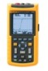
Fluke 124 FE 123 & 124 Users Manual
Fluke 124 Manual
 |
View all Fluke 124 manuals
Add to My Manuals
Save this manual to your list of manuals |
Fluke 124 manual content summary:
- Fluke 124 | FE 123 & 124 Users Manual - Page 1
® Fluke 123/124 Industrial ScopeMeter GB Sep 2002 © 2002 Fluke Corporation. All rights reserved. All product names are trademarks of their respective companies. Users Manual - Fluke 124 | FE 123 & 124 Users Manual - Page 2
- Fluke 124 | FE 123 & 124 Users Manual - Page 3
is three years for the Test Tool and one year for its accessories. The warranty period begins on the date of shipment. Parts, product repairs and services are warranted for 90 days. This warranty extends only to the original buyer or end-user customer of a Fluke authorized reseller, and does not - Fluke 124 | FE 123 & 124 Users Manual - Page 4
SERVICE CENTERS To locate an authorized service center, visit us on the World Wide Web: http://www.fluke.com or call Fluke using any of the phone numbers listed below: +1-888-993-5853 in U.S.A. and Canada +31-402-675-200 in Europe +1-425-446-5500 from other countries - Fluke 124 | FE 123 & 124 Users Manual - Page 5
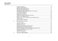
Contents Chapter Title Page Declaration of Conformity ...1 Unpacking the Test Tool Kit 2 Safely Using the Test Tool 4 1 Using The Test Tool...7 Goal of this Chapter ...7 Powering the Test Tool 7 Resetting the Test Tool 8 Changing Backlight ...9 Reading the Screen ...10 Making Selections - Fluke 124 | FE 123 & 124 Users Manual - Page 6
the Test Tool...43 Charging the Rechargeable Battery Pack 44 Keeping Batteries in Optimal Condition 45 Replacing and Disposing of the Rechargeable Battery Pack 46 Using and Adjusting 10:1 Scope Probes 47 Calibrating the Test Tool 49 Parts and Accessories 49 3 Tips and Troubleshooting 53 - Fluke 124 | FE 123 & 124 Users Manual - Page 7
Proper Grounding 59 Solving Printing and Other Communication Errors 60 Battery Testing of Fluke Accessories 60 4 Specifications...61 Introduction ...61 Dual Input Oscilloscope 62 Dual Input Meter...65 Cursor readout (Fluke 124 68 Miscellaneous ...69 Environmental ...70 Safety ...70 iii - Fluke 124 | FE 123 & 124 Users Manual - Page 8
Fluke 123/124 Users Manual iv - Fluke 124 | FE 123 & 124 Users Manual - Page 9
Declaration of Conformity for Fluke 123/124 ScopeMeter® test tool Manufacturer Fluke Industrial B.V. Lelyweg 1 7602 EA Almelo The Netherlands Statement of Conformity Based on test results using appropriate standards, the product is in conformity with Electromagnetic Compatibility Directive 89/336/ - Fluke 124 | FE 123 & 124 Users Manual - Page 10
Fluke 123/124 Users Manual Unpacking the Test Tool Kit The following items are included in your test tool kit. (see Figure 1.): # Description 1 Fluke Test Tool 2 Rechargeable Battery Pack 3 Power Adapter/Battery Charger 4 Shielded Test Leads with Black Ground Leads 5 Test Lead Black (for Grounding) - Fluke 124 | FE 123 & 124 Users Manual - Page 11
1 9 Unpacking the Test Tool Kit 12 2 3 10 4 (2x) 6 (2x) 7 (3x) 5 11 8* Fluke 123/124 * Fluke 123/124 : 1x Fluke 123-S/124-S : 2x 15 Figure 1. ScopeMeter Test Tool Kit 13 14 Fluke 123-S/124-S Fluke 124/124-S 3 - Fluke 124 | FE 123 & 124 Users Manual - Page 12
that pose hazard(s) to the user. Symbols used on the test tool and in this manual are explained in the next table. Warning To avoid electrical shock, use only Fluke power supply, Model PM8907 (Power Adapter/Battery Charger). 4 See explanation in manual Disposal information Equal potential inputs - Fluke 124 | FE 123 & 124 Users Manual - Page 13
the Test Tool, or indicated as suitable for the Fluke 123/124 Test Tool. • Before use, inspect voltage probes, test leads and accessories for mechanical damage and replace when damaged. • Remove all probes, test leads and accessories that are not in use. • Always connect the battery charger first - Fluke 124 | FE 123 & 124 Users Manual - Page 14
Fluke 123/124 Users Manual • Do not insert metal objects into connectors. • Always use the Test Tool only in the manner specified. Max. Input Voltages the test leads for mechanical damage and replace damaged test leads! Whenever it is likely that safety has been impaired, the Test Tool must be - Fluke 124 | FE 123 & 124 Users Manual - Page 15
to use the menus perform basic operations. Powering the Test Tool Follow the procedure (step 1 to 3) in Figure 1-1 to power the test tool from a standard ac outlet. See Chapter 2 for battery power instructions. Turn the test tool on. The test tool powers up in its last setup configuration. Chapter - Fluke 124 | FE 123 & 124 Users Manual - Page 16
Fluke 123/124 Users Manual Resetting the Test Tool If you want to restore the test tool settings as delivered from the factory, do the following: Turn the test tool off. Press and hold. Press and release. The test tool turns on, and you should hear a double beep, indicating the Reset was successful. - Fluke 124 | FE 123 & 124 Users Manual - Page 17
the battery pack (no power adapter connected). Note Using dimmed display lengthens maximum battery power operation time. To change the brightness of the display in Fluke 123, do the following: Dim the backlight. Brighten the backlight again. 1 Using The Test Tool Changing Backlight In Fluke 124, do - Fluke 124 | FE 123 & 124 Users Manual - Page 18
Fluke 123/124 Users Manual Reading the Screen The screen is divided into three areas: Reading area, the condition of the battery from full to empty: . Menu area (C): Displays the menu that provides choices available through the blue function keys. When you change a setup, a part of the screen is - Fluke 124 | FE 123 & 124 Users Manual - Page 19
to to open a menu and to choose an item. Press the SCOPE MENU key to open the Scope menu. 1 Using The Test Tool Making Selections in a Menu Figure 1-4 shows the basic navigation of the test tool. Note Pressing the SCOPE MENU key a second time closes this menu and resumes normal measurement. This - Fluke 124 | FE 123 & 124 Users Manual - Page 20
Fluke 123/124 Users Manual Looking at the Measurement Connections Look at the top of the test tool. The test tool provides two 4-mm always use the red input A for all single input measurements possible with the test tool. Input B For measurements on two different signals you can use the gray input - Fluke 124 | FE 123 & 124 Users Manual - Page 21
Test Tool ™ function, do the following: • Connect the red test lead from red input A to the unknown signal to be measured . Perform an Auto Set. In the next example, the screen displays "1.411" in large numbers and "-0.103" in smaller numbers. A scope - Fluke 124 | FE 123 & 124 Users Manual - Page 22
Fluke 123/124 Users Manual Making Measurements The reading area displays the numeric readings of the chosen measurements on the waveform that is applied to the input jack. • First connect the red shielded test lead from input A, and the gray shielded test lead from input B to the signals to be - Fluke 124 | FE 123 & 124 Users Manual - Page 23
To choose also a Peak-to-Peak measurement for Input B, do the following: Open the INPUT B menu. 1 Using The Test Tool Making Measurements Highlight PEAK-PEAK. Accept the pk-pk measurement. Now, you will see a screen like Figure 1-8. Highlight ON. Turn Input B on. Observe that the - Fluke 124 | FE 123 & 124 Users Manual - Page 24
Fluke 123/124 Users Manual Freezing the Screen You can freeze the screen (all readings and waveforms) at any time. Freeze the screen. HOLD appears at the bottom of the - Fluke 124 | FE 123 & 124 Users Manual - Page 25
you need to monitor the measured value in relation to a known good value. Open the INPUT A menu. Open the METER A OPTIONS submenu. 1 Using The Test Tool Making Relative Measurements (2x) Jump to ZERO REF. Highlight ON. Activate the relative measurement. Figure 1-9. Making a Relative Measurement - Fluke 124 | FE 123 & 124 Users Manual - Page 26
Fluke 123/124 Users Manual Selecting Auto/Manual Ranges Press to automatically adjust the position, range, time on the screen manually. Changing the Amplitude Enlarge the waveform. Reduce the waveform. Available settings are from 5 mV/div to 500 V/div when using the test leads. Observe that - Fluke 124 | FE 123 & 124 Users Manual - Page 27
waveform of INPUT A on the screen. Waveform positioning is demonstrated in Figure 1-10. Observe that the trigger identifier ( ) moves horizontally on the screen. 1 Using The Test Tool Changing the Graphic Representation on the Screen Figure 1-10. Positioning the Waveform 19 - Fluke 124 | FE 123 & 124 Users Manual - Page 28
Fluke 123/124 Users Manual Smoothing the Waveform To smooth the waveform, do the following: Open the SCOPE INPUTS menu. Open the SCOPE OPTIONS submenu. Jump to WAVEFORM MODE. Highlight SMOOTH. Accept waveform smooth. You can use waveform smooth to suppress noise without loss of bandwidth. Waveform - Fluke 124 | FE 123 & 124 Users Manual - Page 29
Displaying the Envelope of a Waveform The test tool records the envelope (minimum and maximum) of the live waveforms A and of input waveforms over a longer period of time. 1 Using The Test Tool Changing the Graphic Representation on the Screen Figure 1-12. Displaying the Envelope of a Waveform 21 - Fluke 124 | FE 123 & 124 Users Manual - Page 30
Fluke 123/124 Users Manual TrendPlotting a Waveform The TrendPlot™ function plots the digital readings as a function of time. Date and time stamp shows the time of the most recent change in a MIN or MAX reading. Starting a TrendPlot™ function Open the INPUT A menu. Start TRENDPLOT. The test tool - Fluke 124 | FE 123 & 124 Users Manual - Page 31
the Waveform Making a Single Acquisition To catch single events, you can perform a single shot. (One time screen update.) To set up the test tool for a single shot on the input A waveform, do the following: • Connect the probe to the signal to be measured. Open the SCOPE INPUTS menu. Open the - Fluke 124 | FE 123 & 124 Users Manual - Page 32
Fluke 123/124 Users Manual Wait appears on bottom of the screen to indicate that the test tool is waiting for a trigger. Run appears on bottom of the screen when the single acquisition is triggered. Hold appears on bottom of the screen when the single acquisition has been completed. The test tool - Fluke 124 | FE 123 & 124 Users Manual - Page 33
visual log of waveform activity and is especially useful when you measure lower frequency waveforms. Open the SCOPE INPUTS menu. Open the SCOPE OPTIONS submenu. 1 Using The Test Tool Acquiring the Waveform Highlight ROLL MODE. (2x) Start Recording. The waveform moves accross the screen from right - Fluke 124 | FE 123 & 124 Users Manual - Page 34
Fluke 123/124 Users Manual Selecting AC-Coupling Use AC-coupling when you wish to observe a small AC signal that rides on a DC signal. Open the SCOPE INPUTS menu. Reversing the Polarity of the Displayed Waveform To invert the input A waveform, do the following: Open the SCOPE INPUTS menu. - Fluke 124 | FE 123 & 124 Users Manual - Page 35
trigger on nearly all signals. To optimize trigger level and slope manually, do the following: Press until you have left any open menu. Enable the arrow keys for Trigger Level and Slope adjustment. 1 Using The Test Tool Triggering on a Waveform Adjust the Trigger Level continuously. Observe the - Fluke 124 | FE 123 & 124 Users Manual - Page 36
Fluke 123/124 Users Manual Selecting the Trigger Parameters To trigger on the input A waveform, with automatic screen update, and to configure the auto range triggering for waveforms from 1 Hz, do the following: Open the SCOPE INPUTS menu. Open the TRIGGER submenu. Accept all trigger selections and - Fluke 124 | FE 123 & 124 Users Manual - Page 37
on an external source, and to isolate the test tool from a trigger waveform. See Figure 1-17. To choose the isolated trigger probe, select 'EXT' in point of the previous example. Trigger level is fixed and is TTL compatible. 1 Using The Test Tool Triggering on a Waveform Triggering on Video Signals - Fluke 124 | FE 123 & 124 Users Manual - Page 38
Fluke 123/124 Users Manual Highlight POSITIVE. Accept the video trigger selections . Trigger level and slope are now fixed. (See Figure 1-18.) Positive video is indicated as a "+" icon on bottom of the screen. Figure 1-18. Measuring Video Signals 30 - Fluke 124 | FE 123 & 124 Users Manual - Page 39
line number. To measure on a selected video line, continue from point of the previous example as follows: Highlight SELECT 1 Using The Test Tool Triggering on a Waveform Pressing selects the line number function. To choose line 135, do the following: Enable video line selection. Select number - Fluke 124 | FE 123 & 124 Users Manual - Page 40
Fluke 123/124 Users Manual Saving and Recalling a Setup and a Screen You can save Screens and Setups to memory, and recall them again for later use. Fluke 123 has 10 memories while Fluke 124 has 20 memories. In each memory you can save a screen and the related settings. Saving Screens with Belonging - Fluke 124 | FE 123 & 124 Users Manual - Page 41
Setups To recall a screen and setups, do the following: Open the SAVE/PRINT menu. Highlight RECALL ... Open the RECALL ... submenu. 1 Using The Test Tool Saving and Recalling a Setup and a Screen Highlight memory 7. View the saved screen and belonging settings. Observe that the recalled waveform is - Fluke 124 | FE 123 & 124 Users Manual - Page 42
Fluke 123/124 Users Manual Deleting Screens and Associated Setups To delete all or just 1 screen + setups, do the following: Open the SAVE/PRINT menu. If you want to clear - Fluke 124 | FE 123 & 124 Users Manual - Page 43
Fluke 124 has cursors. Cursors allow you to make precise digital measurements on waveforms. This can be done on live waveforms and on saved waveforms. Using Horizontal Cursors on a Waveform To use the cursors for a voltage measurement, do the following: From Scope Using The Test Tool Making Cursor - Fluke 124 | FE 123 & 124 Users Manual - Page 44
Fluke 123/124 Users Manual The readout shows the voltage difference between the two cursors Cursors on a Waveform To use the cursors for a time measurement, do the following: From Scope mode, display the Cursor Key functions. Press to highlight . Observe that two vertical cursors are displayed - Fluke 124 | FE 123 & 124 Users Manual - Page 45
measure rise time, do the following: From Scope mode, display the Cursor Key functions. Press MANUAL or AUTO. AUTO automatically does steps 4 to 6. For multiple traces select the required trace A or B. Move the upper cursor to 100% of the trace height. A marker is shown at 90%. 1 Using The Test Tool - Fluke 124 | FE 123 & 124 Users Manual - Page 46
Fluke 123/124 Users Manual The reading now shows the risetime from 10%-90% of the trace amplitude and the voltage at the cursors in relation to the zero icon (-). See Figure 1-21. ~ Turn off the cursors. 38 Using the 10:1 Probe for High Frequency Measurements. Fluke 124 is supplied with a model - Fluke 124 | FE 123 & 124 Users Manual - Page 47
however must be adjusted for optimal High Frequency performance. How to adjust these Probes is explained in Chapter 2 under 'Using and Adjusting 10:1 Scope Probes'. 1 Using The Test Tool Using a Printer Using a Printer To print a (graphic) hard copy of the present screen, you need to use one of - Fluke 124 | FE 123 & 124 Users Manual - Page 48
Fluke 123/124 Users Manual Figure 1-22. Connecting a Serial Printer This example covers how to set up the test tool to print on a HP Deskjet printer with a baudrate of 9600 baud: Open the SAVE&PRINT menu. Observe that the screen is freezed. Open the PRINTER - Fluke 124 | FE 123 & 124 Users Manual - Page 49
/Cable (PM9080) to connect a computer to the OPTICAL PORT of the test tool. See Figure 1-24. For all information relating to installing and using the FlukeView ScopeMeter software, see the SW90W Users Manual. A Software & Cable Carrying Case Kit is optional available as model number SCC 120. 41 - Fluke 124 | FE 123 & 124 Users Manual - Page 50
Fluke 123/124 Users Manual Figure 1-24. Connecting a Computer 42 - Fluke 124 | FE 123 & 124 Users Manual - Page 51
can be performed by the user. For complete service, disassembly, repair, and calibration information, see the Service Manual. You will find the part number of the Service Manual in the section 'Parts and Accessories' in this manual. Cleaning the Test Tool Clean the test tool with a damp cloth and - Fluke 124 | FE 123 & 124 Users Manual - Page 52
123/124 Users Manual Charging the Rechargeable Battery Pack At delivery, the batteries may be empty and must be charged (test tool is off) to fill them completely. Charging time is 5 hours for Fluke 123 (Ni-Cd battery) and 7 hours for Fluke 124 (Ni-MH battery). When fully charged, the batteries - Fluke 124 | FE 123 & 124 Users Manual - Page 53
the operating time for the test tool. You can refresh the battery pack at any time. This battery refresh cycle fully discharges and charges the battery pack. A complete refresh cycle takes about 14 hours (Fluke 123 with Ni-Cd battery) or 19 hours (Fluke 124 with Ni-MH battery) and should be done at - Fluke 124 | FE 123 & 124 Users Manual - Page 54
Fluke 123/124 Users Manual Replacing and Disposing of the Rechargeable Battery Pack Warning To avoid electrical shock, remove the test leads and probes before replacing the battery pack. Note This instrument contains Ni-Cd or Ni-MH batteries. Do not dispose of this battery pack with other solid - Fluke 124 | FE 123 & 124 Users Manual - Page 55
time) battery pack. For Fluke 124 it is recommended to use the Fluke BP130 Ni-MH battery pack . 8. Reinstall the battery cover and secure the screw. Using and Adjusting 10:1 Scope Probes Note The 10:1 voltage probe that is supplied with Fluke 124 is always adjusted correctly to the Test Tool and - Fluke 124 | FE 123 & 124 Users Manual - Page 56
Fluke 123/124 Users Manual Open the SCOPE INPUTS menu. Open the PROBES submenu. Highlight PROBE AC ADJUST. Open the PROBE AC ADJUST submenu. Highlight ADJUST 10:1 PROBE. A square wave appears on the screen. 48 Adjust the trimmer screw in the probe housing to give an optimum square wave. Return - Fluke 124 | FE 123 & 124 Users Manual - Page 57
the VERSION&CALIBRATION submenu. 2 Maintaining the Test Tool Calibrating the Test Tool Parts and Accessories Service Manual Ordering Number: 4822 872 05389 Standard Accessories The next tables list the user-replaceable parts for the various test tool models. To order replacement parts, contact your - Fluke 124 | FE 123 & 124 Users Manual - Page 58
Fluke 123/124 Users Manual Standard Accessories (cont) Item Ni-Cd Battery Pack (installed in Fluke 123, 123/S) Ni-MH Battery Pack (installed in Fluke 124, 124/S) Power Adapter/Battery Charger, available models: Universal Europe 230V, 50Hz North America 120V, 60Hz United Kingdom 240V, 50Hz Japan 100V - Fluke 124 | FE 123 & 124 Users Manual - Page 59
, Portuguese, Italian, Dutch, Danish, Norwegian, Swedish, Finnish, Russian) Getting Started Manual (English, Chinese, Japanese, Korean) CD-ROM with Users Manual (All languages) 2 Maintaining the Test Tool Parts and Accessories Ordering Code TL75 HC120 AC120 BB120 (Set of two) BB120 (set of two - Fluke 124 | FE 123 & 124 Users Manual - Page 60
Users Manual Optional Accessories Item Software & Cable Carrying Case Kit (Supplied with Fluke 123/S, 124/S) Set contains the following parts: Optically Isolated RS-232 Adapter/Cable Hard Carrying Case. Supplied with Fluke 123/S, 124/S FlukeView® ScopeMeter® Software for Windows® 10:1 Scope Probe - Fluke 124 | FE 123 & 124 Users Manual - Page 61
3 Tips and Troubleshooting Goal of this Chapter This Chapter gives you information and tips on how you can make the best use of the test tool. Using the Tilt Stand The test tool is equipped with a tilt stand, allowing viewing from an angle. You can also use the tilt stand to hang the test tool at - Fluke 124 | FE 123 & 124 Users Manual - Page 62
Fluke 123/124 Users Manual Resetting the Test Tool Perform a Master Reset to make sure that your test tool is in the initial settings condition. Turn the test tool off. Press and hold. Press and release. The test tool turns on, and you should hear a double beep, indicating the Reset was successful. - Fluke 124 | FE 123 & 124 Users Manual - Page 63
in Fluke 123 From the main menu, choose CONTRAST. Adjust the contrast of the screen. Adjusting the Screen Contrast in Fluke 124 Switch made. 3 Tips and Troubleshooting Changing the Display Setting the Grid Display To choose a dotted grid, do the following: Open the USER OPTIONS menu. Highlight GRID - Fluke 124 | FE 123 & 124 Users Manual - Page 64
Fluke 123/124 Users Manual Changing Date and Time The test tool has a date and time clock. To change the date to (e.g.) 20 June, 2002, do the following: Open USER OPTIONS menu. Highlight DATE ADJUST. Open DATE ADJUST submenu. Jump to DAY. Choose 20. Jump to FORMAT. Choose DD/MM/YY. Accept the new - Fluke 124 | FE 123 & 124 Users Manual - Page 65
battery pack (no Power Adapter connected), the test tool conserves power by shuting itself down. If you have not pressed a key for at least 30 minutes, the test tool the following: Open the USER OPTIONS menu. Highlight POWER DOWN ... 3 Tips and Troubleshooting Saving Battery Life Open the submenu. - Fluke 124 | FE 123 & 124 Users Manual - Page 66
Fluke 123/124 Users Manual Changing the Auto Set Options Normally, the Auto Set function captures waveforms from 15 Hz. To configure Auto Set for waveforms from 1 Hz with unchanged - Fluke 124 | FE 123 & 124 Users Manual - Page 67
Incorrect grounding can cause various problems. This Section gives you guidelines for proper grounding. Use the short ground lead(s) when measuring DC or unshielded ground lead. 3 Tips and Troubleshooting Using Proper Grounding Figure 3-2. Grounding with Short Ground Lead Figure 3-3. Grounding - Fluke 124 | FE 123 & 124 Users Manual - Page 68
Fluke 123/124 Users Manual Solving Printing and Other Communication Errors RS-232 communication may cause problems. When experiencing communication problems, try the following remedies: Make sure that the interface cable is connected to the correct port on the printer or computer. If necessary use - Fluke 124 | FE 123 & 124 Users Manual - Page 69
of a range of identical ScopeMeter test tools. Environmental Data The environmental data mentioned in this manual are based on the results Measurement, Control, and Laboratory Use. This manual contains information and warnings that must be followed by the user to ensure safe operation and to keep the - Fluke 124 | FE 123 & 124 Users Manual - Page 70
Fluke 123/124 Users Manual Dual Input Oscilloscope Vertical Frequency Response DC Coupled: excluding probes and test leads (via BB120 Fluke 123: DC to 20 MHz (-3 dB) Fluke 124: DC to 40 MHz (-3 dB) with STL120 1:1 shielded test leads DC to 12.5 MHz (-3 dB) DC to 20 MHz (-6 dB) with VP40 10:1 probe - Fluke 124 | FE 123 & 124 Users Manual - Page 71
Input Oscilloscope Trigger Screen Update Free Run, On Trigger Source A, B, EXT EXTernal via optically isolated trigger probe ITP120 (optional accessory) Sensitivity A and B (Fluke 123) @ DC to 5 MHz 0.5 divisions or 5 mV @ 25 MHz 1.5 divisions @ 40 MHz 4 divisions Sensitivity A and B (Fluke 124 - Fluke 124 | FE 123 & 124 Users Manual - Page 72
Fluke 123/124 Users Manual Advanced Scope Functions Display Modes Normal........Captures up to 40 ns glitches and displays analog-like persistence waveform. Smooth.......Suppresses noise from a waveform. Envelope ....Records and displays - Fluke 124 | FE 123 & 124 Users Manual - Page 73
) 4 Specifications Dual Input Meter 5 MHz to 12.5 MHz 30% +25 counts) 5 MHz to 20 MHz (excl. test leads or probes) .......... ±(30% +25 counts) AC coupled with 1:1 (shielded) test leads 60 Hz (6 Hz with 10:1 probe 1.5% 50 Hz (5 Hz with 10:1 probe 2% 33 Hz (3.3 Hz with 10:1 probe 5% 10 Hz (1 Hz - Fluke 124 | FE 123 & 124 Users Manual - Page 74
Fluke 123/124 Users Manual Accuracy: @1 Hz to 1 MHz 0.5% +2 counts) @1 to 10 MHz 1.0% +2 counts) @10 to 50 MHz (Fluke 123 2.5% +2 counts) @10 to 70 MHz (Fluke 124 ) Full Scale Reading 1000 counts Amperes (AMP with optional current probe Ranges......... same as VDC, VAC, VAC+DC, or PEAK Scale - Fluke 124 | FE 123 & 124 Users Manual - Page 75
) Ranges 50 nF, 500 nF, 5 µF, 50 µF, 500 µF Accuracy 2% +10 counts) Full Scale Reading 5000 counts 4 Specifications Dual Input Meter Measurement Current 5 µA to 0.5 mA increases with increasing ranges Dual slope integrating measurement with parasitic serial and parallel resistance cancellation - Fluke 124 | FE 123 & 124 Users Manual - Page 76
Fluke 123/124 Users Manual Advanced Meter Functions Zero Set Set actual value to reference Fast/Normal/Smooth Meter settling time Fast: 1s @ 1 µs to 10 ms/div. Meter settling time Normal: 2s @ 1 µs to 10 ms/div. Meter settling time Smooth: 10s @ 1 µs to 10 ms/div. Touch Hold (on A) Captures and - Fluke 124 | FE 123 & 124 Users Manual - Page 77
jack Fluke 123 (Internal Battery Pack BP120): Battery Power Rechargeable Ni-Cd 4.8V Operating Time 4 hours with bright backlight 4.25 hours with dimmed backlight Charging Time 5 hours with test tool off 40 hours with test tool on 9 .. 14 hours with refresh cycle Fluke 124 (Internal Battery Pack - Fluke 124 | FE 123 & 124 Users Manual - Page 78
Fluke 123/124 Users Manual Environmental Environmental MIL-PRF-28800F, Class 2 Temperature Operating 0 to 50 °C UL3111-1 (including approval) Max. Input Voltage Input A and B Direct on input or with leads 600 Vrms for derating, see Figure 4-1. With Banana-to BNC Adapter BB120 300 Vrms for - Fluke 124 | FE 123 & 124 Users Manual - Page 79
4 Specifications Safety Figure 4-1. Max. Input Voltage v.s. Frequency for BB120 and STL120 Figure 4-2. Max. Input Voltage v.s. Frequency for VP40 10:1 Voltage Probe 71 - Fluke 124 | FE 123 & 124 Users Manual - Page 80
Fluke 123/124 Users Manual The Fluke 123/124, including standard accessories, conforms with the EEC directive 89/336 for EMC immunity, 100 mV/div to 200 mV/div - (-): no visible disturbance Test tool ranges not specified in tables 1 and 2 may have a disturbance of more than 10% of full scale. - Fluke 124 | FE 123 & 124 Users Manual - Page 81
, and VAC+DC with STL120 and short ground lead. • OHM, CONT, DIODE, and CAP with STL120, and black test lead to COM. Table 3 Disturbance less than 1% to 500 µF 500 mV to 1250V 500Ω to 30 MΩ 50 nF to 500 µF Test tool ranges not specified in table 3 may have a disturbance of more than 10% of full - Fluke 124 | FE 123 & 124 Users Manual - Page 82
Fluke 123/124 Users Manual 74 - Fluke 124 | FE 123 & 124 Users Manual - Page 83
Battery Pack, 2, 44, 50 Battery Power, 69 Battery Refresh Date, 49 Battery Replacing, 46 BB120 Adapters, 51 Blue Function Keys, 10 BP120 Battery Pack, 47, 50 BP130 Battery Pack, 47, 50 Bright Display, 9 -C- C120 Hard Case, 52 C125 Compact Soft Case, 52 C789 Soft Case, 52 Calibrating the Test Tool - Fluke 124 | FE 123 & 124 Users Manual - Page 84
Fluke 123/124 Users Manual Charge Time, 69 Charger, 50 Charging, 44 Cleaning, 43 Common, 12 Communication Errors, 60 Compact Soft Case 59, 67 Display, 55, 69 Disposing Batteries, 46 Duty Cycle, 66 76 -E- Ground Test Lead, 51 Grounding Problems, 59 -H- Hands-free Measurements, 16 Hard Carrying Case, - Fluke 124 | FE 123 & 124 Users Manual - Page 85
Meter A Measurement, 14 Meter B Measurement, 15 Min Max Reading, 23 Minimum (MIN) Reading, 22 Multimeter Disturbance, 73 -N- Ni-Cd Battery Pack, 2, 44, 50 Ni-MH Battery Pack Batteries, 49 Relative Measurements, 17 Replaceable Parts, 49 Replacing Batteries, 46 Resetting, 54 Resetting the Test Tool, - Fluke 124 | FE 123 & 124 Users Manual - Page 86
41, 52 Scope Modes, 63 Scope Probes, 52 Screen Contrast, 55 Selecting Trigger Parameters, 28 Sensitivity, 62 Serial Printer, 40 Service Manual, 49 Shielded Test Leads, 50 Shock, 70 Single Shot, 23 Slope, 27, 63 Slow Signals, 25 Smooth, 20, 64 Soft Carrying Case, 52 Software, 52 78 Software Version
-
 1
1 -
 2
2 -
 3
3 -
 4
4 -
 5
5 -
 6
6 -
 7
7 -
8
-
9
-
10
-
11
-
12
-
13
-
14
-
15
-
16
-
17
-
18
-
19
-
20
-
21
-
22
-
23
-
24
-
25
-
26
-
27
-
28
-
29
-
30
-
31
-
32
-
33
-
34
-
35
-
36
-
37
-
38
-
39
-
40
-
41
-
42
-
43
-
44
-
45
-
46
-
47
-
48
-
49
-
50
-
51
-
52
-
53
-
54
-
55
-
56
-
57
-
58
-
59
-
60
-
61
-
62
-
63
-
64
-
65
-
66
-
67
-
68
-
69
-
70
-
71
-
72
-
73
-
74
-
75
-
76
-
77
-
78
-
79
-
80
-
81
-
82
-
83
-
84
-
85
-
86
 |
 |

GB
Sep 2002
© 2002 Fluke Corporation. All rights reserved.
All product names are trademarks of
their respective companies.
®
Fluke 123/124
Industrial ScopeMeter
Users Manual