Foxconn M61PMV English Manual. - Page 21
Front Panel Connector : FP1, USB Connectors : F_USB1/2, Serial ATA Connectors : SATA_1/2/3/4, IDE - support
 |
View all Foxconn M61PMV manuals
Add to My Manuals
Save this manual to your list of manuals |
Page 21 highlights
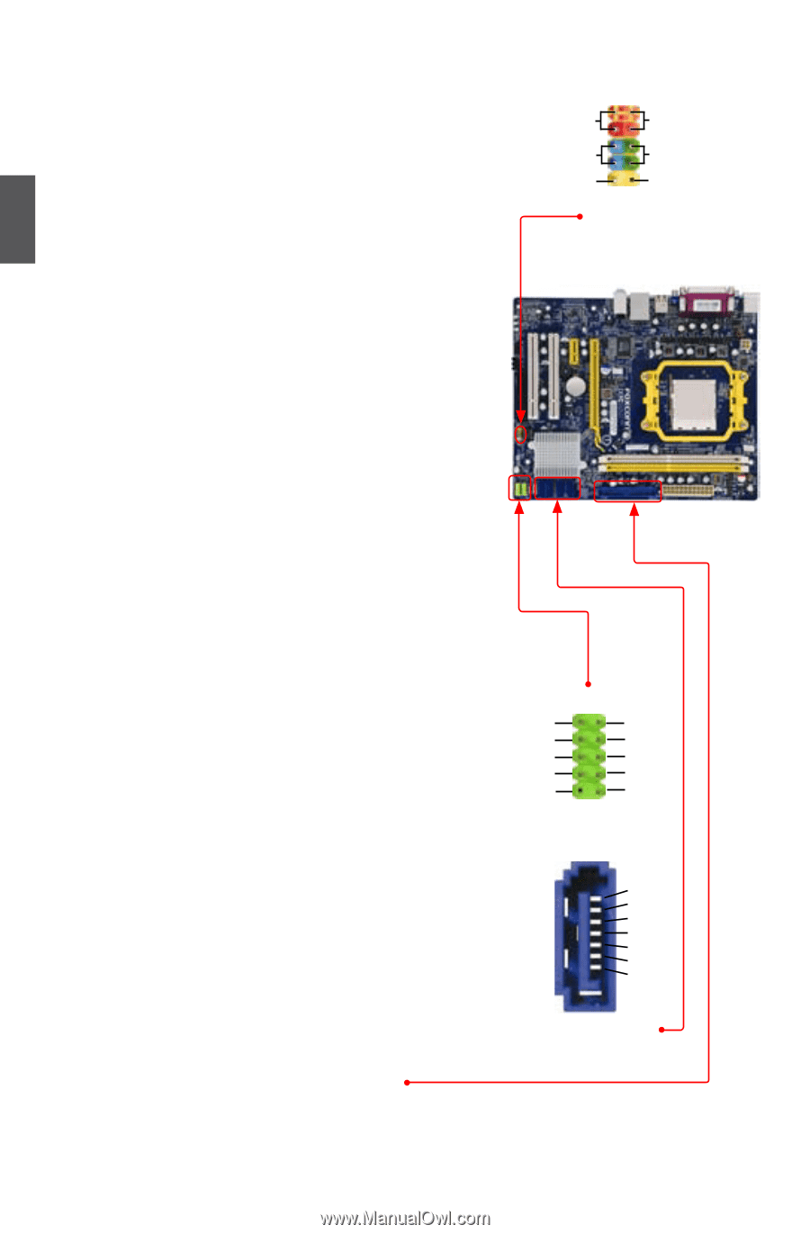
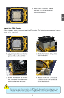
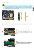
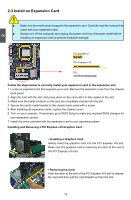
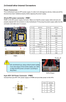
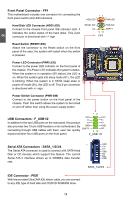
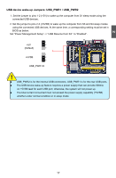
2 Front Panel Connector : FP1 This motherboard includes one connector for connecting the front panel switch and LED Indicators. Hard Disk LED Connector (HDD-LED) Connect to the chassis front panel IDE indicator LED. It indicates the active status of the hard disks. This 2-pin connector is directional with +/- sign. 12 + + HDD-LED - PWR-LED - RESET-SW PWR-SW NC EMPTY 9 10 FP1 Reset Switch (RESET-SW) Attach the connector to the Reset switch on the front panel of the case; the system will restart when the switch is pressed. Power LED Connector (PWR-LED) Connect to the power LED indicator on the front panel of the chassis. The Power LED indicates the system's status. When the system is in operation (S0 status), the LED is on. When the system gets into sleep mode (S1) , the LED is blinking; When the system is in S3/S4 sleep state or power off mode (S5), the LED is off. This 2-pin connector is directional with +/- sign. Power Switch Connector (PWR-SW) Connect to the power button on the front panel of the chassis. Push this switch allows the system to be turned on and off rather than using the power supply button. 12 USB Connectors : F_USB1/2 VCC D- VCC D- In addition to the two USB ports on the rear panel, this product D+ D+ also provides two 10-pin USB headers on its motherboard. By GND GND connecting through USB cables with them, user can quickly EMPTY NC 9 10 expand another four USB ports on the front panel. F_USB 1/2 Serial ATA Connectors : SATA_1/2/3/4 The Serial ATA connector is used to connect with SATA Hard Disk or CD devices which support this feature. The current Serial ATA II interface allows up to 300MB/s data transfer rate. 1 GND TX+ TX- GND RX- RX+ GND SATA_1/2/3/4 IDE Connector : PIDE With the provided Ultra DMA IDE ribbon cable, you can connect to any IDE type of hard disk and CD/DVD ROM/RW drive. 14
-
 1
1 -
2
-
3
-
4
-
5
-
6
-
7
-
8
-
9
-
10
-
11
-
12
-
13
-
14
-
15
-
 16
16 -
 17
17 -
 18
18 -
 19
19 -
 20
20 -
 21
21 -
 22
22 -
 23
23 -
 24
24 -
 25
25 -
 26
26 -
27
-
28
-
29
-
30
-
31
-
32
-
33
-
34
-
35
-
36
-
37
-
38
-
39
-
40
-
41
-
42
-
43
-
44
-
45
-
46
-
47
-
48
-
49
-
50
-
51
-
52
-
53
-
54
-
55
-
56
-
57
-
58
-
59
-
60
-
61
-
62
-
63
-
64
-
65
-
66
-
67
-
68
-
69
-
70
-
71
-
72
-
73
-
74
-
75
-
76
-
77
-
78
-
79
-
80
-
81
-
82
-
83
-
84
-
85
-
86
-
87
-
88
-
89
-
90
-
91
-
92
-
93
-
94
-
95
-
96
-
97
-
98
-
99
-
100
-
101
-
102
-
103
-
104
-
105
-
106
-
107
-
108
 |
 |