Foxconn M61PMV English Manual. - Page 22
Audio Connector : F_AUDIO, Audio Connector : CD_IN, Chassis Intruder Connector : INTR, S/PDIF
 |
View all Foxconn M61PMV manuals
Add to My Manuals
Save this manual to your list of manuals |
Page 22 highlights
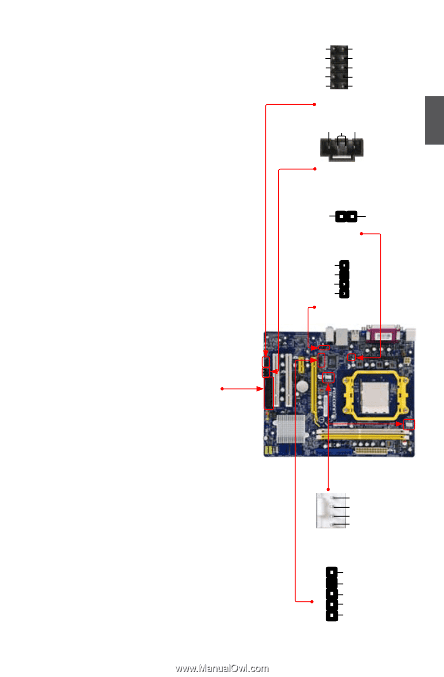
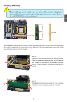
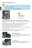
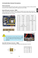
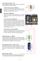
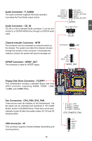
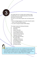
2 Audio Connector : F_AUDIO The audio connector supports HD Audio standard. It provides the Front Audio output choice. Audio Connector : CD_IN CD_IN is a Sony standard audio connector, it can be connected to a CD/DVD-ROM drive through a CD/DVD audio cable. 12 PORT1_L AUD_GND PORT1_R PRESENCE_J PORT2_R SENSE1_RETURN SENSE_SEND EMPTY PORT2_L SENSE2_RETURN 9 10 F_AUDIO CD_L GND CD_R 1 CD_IN Chassis Intruder Connector : INTR The connector can be connected to a security switch on the chassis. The system can detect the chassis intrusion through the function of this connector. If eventually the chassis is closed, the system will send a message out. S/PDIF Connector : SPDIF_OUT The connector is used for S/PDIF output. 1 INTRUDERJ GND INTR +5V 1 EMPTY 2 SPDIF_OUT 3 GND 4 SPDIF_OUT Floppy Disk Drive Connector : FLOPPY This motherboard includes a standard floppy disk drive (FDD) connector, supporting 360KB, 720KB, 1.2MB, 1.44MB, and 2.88MB FDDs. Fan Connectors : CPU_FAN, SYS_FAN There are two main fan headers on this motherboard. The fan speed can be controlled and monitored in "PC Health Status" section of the BIOS Setup. These fans can be automatically turned off after the system enters S3, S4 and S5 sleeping states. IrDA Connector : IR This connector supports infrared wireless transmitting and receiving device. 15 1 GND POWER SENSE CONTROL CPU_FAN/SYS_FAN 1 2 3 4 5 IR +5V EMPTY IRRX GND IRTX
-
 1
1 -
2
-
3
-
4
-
5
-
6
-
7
-
8
-
9
-
10
-
11
-
12
-
13
-
14
-
15
-
16
-
 17
17 -
 18
18 -
 19
19 -
 20
20 -
 21
21 -
 22
22 -
 23
23 -
 24
24 -
 25
25 -
 26
26 -
 27
27 -
28
-
29
-
30
-
31
-
32
-
33
-
34
-
35
-
36
-
37
-
38
-
39
-
40
-
41
-
42
-
43
-
44
-
45
-
46
-
47
-
48
-
49
-
50
-
51
-
52
-
53
-
54
-
55
-
56
-
57
-
58
-
59
-
60
-
61
-
62
-
63
-
64
-
65
-
66
-
67
-
68
-
69
-
70
-
71
-
72
-
73
-
74
-
75
-
76
-
77
-
78
-
79
-
80
-
81
-
82
-
83
-
84
-
85
-
86
-
87
-
88
-
89
-
90
-
91
-
92
-
93
-
94
-
95
-
96
-
97
-
98
-
99
-
100
-
101
-
102
-
103
-
104
-
105
-
106
-
107
-
108
 |
 |