Fujitsu MAF3364LC Manual/User Guide
Fujitsu MAF3364LC - Enterprise 36.4 GB Hard Drive Manual
 |
View all Fujitsu MAF3364LC manuals
Add to My Manuals
Save this manual to your list of manuals |
Fujitsu MAF3364LC manual content summary:
- Fujitsu MAF3364LC | Manual/User Guide - Page 1
MAF3364LC/LP/MC/MP SERIES MAE3182LC/LP, MAE3091LC/LP SERIES MAG3182LC/LP/MC/MP, MAG3091LC/LP/MC/MP SERIES DISK DRIVES PRODUCT MANUAL C141-E064-03EN - Fujitsu MAF3364LC | Manual/User Guide - Page 2
RECORD Edition Date published Revised contents 01 Nov., 1998 02 May, 1999 03 Oct., 1999 MC/MP types are added. Specification No.: C141-E064-**EN The contents of this manual is subject to change without prior notice. All Rights Reserved. Copyright © 1999 FUJITSU LIMITED C141-E064-03EN i - Fujitsu MAF3364LC | Manual/User Guide - Page 3
This page is intentionally left blank. - Fujitsu MAF3364LC | Manual/User Guide - Page 4
keep it carefully. FUJITSU makes every effort to prevent users and bystanders from being injured or from suffering damange to their property. Use the product according to this manual. Functional Limitations There may be certain functional limitations concerning the specifications and functions of - Fujitsu MAF3364LC | Manual/User Guide - Page 5
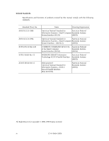
Related Standards Specifications and functions of products covered by this manual comply with the following standards. Standard (Text) No. ANSI X3.131-1986 ANSI X3.131-1994 X3T9.2/85-52 Rev 4.B X3T9.2 855D Rev 12 X3T10/ - Fujitsu MAF3364LC | Manual/User Guide - Page 6
MAF3364LC/LP/MC/MP (hereafter, MAF series), MAE3182LC/LP, MAE3091LC/LP, (hereafter, MAE series), and MAG3182LC/LP/MC/MP, MAG3091LC/LP/MC/MP (hereafter, MAG series), 3.5-inch fixed disk drives with an embedded SCSI controller. This manual details the specifications and functions of the above disk - Fujitsu MAF3364LC | Manual/User Guide - Page 7
or perform the procedure correctly. IMPORTANT IMPORTANT indicates information that the helps the user use the product more effectively. Indicates This manual indicates; Decimal number: Indicates as it is. Hexadecimal number: Indicates as X'17B9', 17B9h, or 17B9H Binary number: Indicates as "010" vi - Fujitsu MAF3364LC | Manual/User Guide - Page 8
environmental conditions, power trouble, host problems, cable failures, or any failure not caused by the drive itself. The suffix of the model name of the disk drive varies depending on the electrical requirements, capacity, and data format at factory shipment of the SCSI, i.e., the interface for - Fujitsu MAF3364LC | Manual/User Guide - Page 9
Alert Messages The important alert messages in this manual are as follows: Task Mounting Installation A hazarous Data loss Save data stored on the disk drive before requesting repair. Fujitsu does not assume responsibility if data is destroyed during servicing or repair. Page 4-10 5-5 5-11 6-4 - Fujitsu MAF3364LC | Manual/User Guide - Page 10
PRODUCT MANUAL (This manual) SCSI Physical Interface Specifications SCSI Logical Interface Specifications Maintenance Manual 1. General Description 2. Specifications 3. Data Format 4. Installation Requirements 5. Installation 6. Diagnostics and Maintenance 1. SCSI Bus 2. SCSI Message 3. SCSI Bus - Fujitsu MAF3364LC | Manual/User Guide - Page 11
This page is intentionally left blank. - Fujitsu MAF3364LC | Manual/User Guide - Page 12
Configuration...1-10 CHAPTER 2 SPECIFICATIONS 2-1 2.1 Hardware Specifications 2-1 2.1.1 Model name and part number 2-1 2.1.2 Function specifications 2-2 2.1.3 Environmental specifications 2-4 2.1.4 Error rate...2-5 2.1.5 Reliability ...2-5 2.2 SCSI Function Specifications 2-7 CHAPTER 3 DATA - Fujitsu MAF3364LC | Manual/User Guide - Page 13
68 pin connector 16-bit model (LP/MP 4-16 SCA2 type SCSI model (LC/MC 4-24 Cable connector requirements 4-28 External operator panel 4-29 CHAPTER 5 INSTALLATION 5-1 5.1 Notes on Handling Drives 5-1 5.2 Connections...5-3 5.3 Setting Terminals...5-5 5.3.1 SCSI ID setting...5-6 5.3.2 Each mode - Fujitsu MAF3364LC | Manual/User Guide - Page 14
Terminals...B-2 APPENDIX C CONNECTOR SIGNAL ALLOCATION C-1 C.1 SCSI Connector Signal Allocation: SCA2 type LVD 16-bit SCSI C-2 C.2 SCSI Connector Signal Allocation: 68 pin type LVD 16-bit SCSI C-3 APPENDIX D MODEL NAMES AND PRODUCT NUMBERS D-1 D.1 Model Names and Product Numbers D-2 Index...IN - Fujitsu MAF3364LC | Manual/User Guide - Page 15
Mounting frame structure 4-9 4.9 Limitation of side-mounting 4-9 4.10 Surface temperature measurement points (MAF series, MAE series, MAG series)........ 4-10 4.11 Service clearance area...4-11 4.12 Air pressure adjustment hole 4-12 4.13 Current waveform (+12 VDC 4-13 4.14 Power on/off sequence - Fujitsu MAF3364LC | Manual/User Guide - Page 16
4.17 AC noise filter (recommended 4-15 4.18 Connectors and terminals location (LP/MP 4-16 4.19 16-bit SCSI interface connector 4-17 4.20 Power supply connector (16-bit SCSI model 4-17 4.21 External operator panel connector (CN1 4-18 4.22 External operator panel connector (CN2 4-19 4.23 16-bit - Fujitsu MAF3364LC | Manual/User Guide - Page 17
2.2 Environmental/power requirements 2-4 2.3 SCSI function specifications 2-7 3.1 Zone layout and track capacity (MAE series 3-3 3.2 Zone layout and track capacity (MAG series 3-3 3.3 Zone layout and track capacity (MAF series 3-3 3.4 Format capacity ...3-10 4.1 Surface temperature check point - Fujitsu MAF3364LC | Manual/User Guide - Page 18
1.2 Hardware Structure 1.3 System Configuration This chapter describes the feature and configuration of the intelligent disk drives (IDD). IDDs are high performance large capacity 3.5-inch fixed disk drives with an embedded SCSI controller. The interface between the IDD and host system is based on - Fujitsu MAF3364LC | Manual/User Guide - Page 19
set which meets the logical specification of the SCSI CCS (Common Command Set for Direct Access Device) requirements (Rev. 4.B) The SCSI commands can manipulate data through logical block addressing regardless of the physical characteristics of the disk drive. This allows software to accommodate - Fujitsu MAF3364LC | Manual/User Guide - Page 20
high data transfer capability of the SCSI bus regardless of actual data transfer rate of the disk drive. (7) Read-ahead cache feature After realizes the high speed processing. Recordering algorithm is adopted to prevent a specific command from staying in a queue for more than 3 seconds. (9) - Fujitsu MAF3364LC | Manual/User Guide - Page 21
inch disk drives by dividing all cylinders into several partitions and changing the recording density on each partition (constant density recording). The disk subsystem with large capacity can be constructed in the good space efficiency. (16) Start/Stop of spindle motor Using the SCSI command, the - Fujitsu MAF3364LC | Manual/User Guide - Page 22
(18) Low power consumption By using highly integrated LSI components, the power consumption of the IDD is very low, and this enables the unit to be used in wide range of environmental conditions. (19) Low noise and low vibration The noise level is low; approx. 4.2 bels for MAF series and 4.0 bels - Fujitsu MAF3364LC | Manual/User Guide - Page 23
Figure 1.2 MAF series LP/MP outer view Figure 1.3 MAE series LC outer view 1 - 6 C141-E064-03EN - Fujitsu MAF3364LC | Manual/User Guide - Page 24
Figure 1.4 MAE series LP outer view Figure 1.5 MAG series LC/MC outer view Figure 1.6 MAG series LP/MP outer view C141-E064-03EN 1 - 7 - Fujitsu MAF3364LC | Manual/User Guide - Page 25
and 25 mm (0.98 inch) inner diameter for MAF/MAG series. The disks are good for at least 15,000 contact starts and stops. Each model contains following number of disks. MAF3364: 10 MAE3182: 4 MAE3091: 2 MAG3182: 5 MAG3091: 3 (2) Heads The MR (Magnet - Resistive) of the CSS (contact start/stop) type - Fujitsu MAF3364LC | Manual/User Guide - Page 26
The disks are rotated by a direct-drive hall-less DC motor. The motor speed write circuit utilizes a read channel mounted with a head IC that supports high-speed transmission and an EPR4ML (Extended Partial Response Class 4 to increase the performance of the SCSI controller. C141-E064-03EN 1 - 9 - Fujitsu MAF3364LC | Manual/User Guide - Page 27
the SCSI bus for the 8-bit SCSI and up to 16 SCSI devices operating as an initiator or a target can be connected to the SCSI bus for the 16-bit SCSI host computers that operate as initiator or connected through the SCSI bus. Using disconnect/reconnect function, concurrent input/output processing is - Fujitsu MAF3364LC | Manual/User Guide - Page 28
. The IDD is constructed so that the whole volume of disk drive is a single logical unit, the selectable number of SCSI ID and LUN are as follows: • SCSI ID: 8-bit SCSI:Selectable from 0 to 7 (switch selectable) 16-bit SCSI:Selectable from 0 to 15 (switch selectable) • LUN: 0 (fixed) C141-E064 - Fujitsu MAF3364LC | Manual/User Guide - Page 29
This page is intentionally left blank. - Fujitsu MAF3364LC | Manual/User Guide - Page 30
CHAPTER 2 SPECIFICATIONS 2.1 Hardware Specifications 2.2 SCSI Function Specifications This chapter describes specifications of the IDD and the functional specifications of the SCSI. 2.1 Hardware Specifications 2.1.1 Model name and part number Each model has a different data format and front panel - Fujitsu MAF3364LC | Manual/User Guide - Page 31
Width Depth Weight Power consumption (*5) Interface Fast SCSI (Single-Ended) Fast 20 SCSI (Single-Ended) Fast 80 SCSI (LVD) Data transfer rate (*10) Disk drive SCSI Synchronous mode Logical data block length (*1) SCSI command specification Data buffer MAE3182 series MAE3091 series 18 - Fujitsu MAF3364LC | Manual/User Guide - Page 32
(*1) The formatted capacity can be changed by changing the logical block length and This value indicates at ready mode. (*6) Up to 4 SCSI devices having capacitance of 25pF or less can use cable length of up to 3.0 m. (*7) 5 to 8 SCSI devices having capacitance of 25pF or less can use cable length - Fujitsu MAF3364LC | Manual/User Guide - Page 33
Environmental specifications Table mVp-p (*1) For detail condition, see Section 4.1. (*2) Vibration applied to the drive is measured at near the mounting screw hole on the frame as much as at the connector. (*6) The terminator power pin (SCSI connector) which supplies power to other terminators is - Fujitsu MAF3364LC | Manual/User Guide - Page 34
conditions, power trouble, host system trouble, cable failures, or other failures not caused by the equipment are not considered. (2) Mean Time To Repair (MTTR) MTTR is the average time taken by a well-trained service mechanic to diagnose and repair a drive malfunction. The drive is designed for - Fujitsu MAF3364LC | Manual/User Guide - Page 35
suitable conditions and treatment is as follows. The service life is depending on the environment temperature. surface temperature is 55°C or less. Even if the IDD is used intermittently, the longest service life is 5 years. Note: The "average DE surface temperature" means the average temperature at - Fujitsu MAF3364LC | Manual/User Guide - Page 36
SCSI Function Specifications Table 2.3 shows the SCSI functions provided with the IDD. Table 2.3 SCSI function specifications Item Specification function Ο Addressing SCSI ID 16-bit SCSI LUN (logical unit number) #0 to #15 (Jumper selection) #0 fixed Data transfer 8-bit SCSI (Single-Ended - Fujitsu MAF3364LC | Manual/User Guide - Page 37
This page is intentionally left blank. - Fujitsu MAF3364LC | Manual/User Guide - Page 38
test, but user can't use direct access. The system space is accessed inside the IDD at power-on or during the execution of a specific command, but the user cannot directly access the system space. 3.1.1 Cylinder configuration The IDD allocates cylinders to the user space, Internal test space - Fujitsu MAF3364LC | Manual/User Guide - Page 39
are explained in Subsection 3.1.3.) Figure 3.1 Cylinder configuration Apart from the above logical configuration, the IDD intends to increase the storage capacity by dividing all cylinders into several zones and changing a recording density of each zone. Tables 3.1 and 3.3 show the zone layout - Fujitsu MAF3364LC | Manual/User Guide - Page 40
11,880 to 11,999 143,360 280 Table 3.2 Zone layout and track capacity (MAG series) Zone 0 Cylinder 0 to 679 Byte/track 215,040 Sector/ 600 300 13 9,150 to 9,865 139,776 273 Table 3.3 Zone layout and track capacity (MAF series) Zone 0 Cylinder 0 to 899 Byte/track 215,040 Sector/track 420 - Fujitsu MAF3364LC | Manual/User Guide - Page 41
(1) User space The user space is a storage area for user data. The data format on the user space (the length of data block and the number of data blocks) can be specified with the MODE SELECT or MODE SELECT EXTENDED command. The default number of cylinders in the user space is 10,200 for MAF series, - Fujitsu MAF3364LC | Manual/User Guide - Page 42
3.1.2 Alternate spare area The alternate spare area is provided in the last track of each primary cylinder in the user space, and in the last track of the cylinder and the alternate cylinder. The spare area in each cylinder is placed at the end of the last track as shown in Figure 3.2. These spare - Fujitsu MAF3364LC | Manual/User Guide - Page 43
3.1.3 Track format (1) Physical sector allocation Figure 3.4 shows the allocation of the physical sectors in a track. The length in bytes of each physical sector and the number of sectors per track vary depending on the logical data block length. The unused area (G4) exists at the end of the track - Fujitsu MAF3364LC | Manual/User Guide - Page 44
Figure 3.5 Track skew/cylinder skew The number of physical sectors (track skew factor and cylinder skew factor) corresponding to the skew time varies depending on the logical data block length because the track skew and the cylinder skew are managed for individual sectors. The IDD automatically - Fujitsu MAF3364LC | Manual/User Guide - Page 45
and a gap field which separates them. Figure 3.6 gives sector format examples. LC/LP models SCT SB LBA PLO G1 Sync 4 4 DATA m BCRC ECC SCT 2 40 PAD PAD 4 4 PAD PAD 12 PLO G1 Sync 4 2 40 PAD PAD 13 MC/MP models SCT SB PLO G1 Sync 4 DATA m BCRC ECC SCT 4 40 PAD PAD 12 - Fujitsu MAF3364LC | Manual/User Guide - Page 46
in this field, but it is not written with MP/MC models because it is appended to BCRC field information. (5) Data field User 4-byte error detection code appended the LBA field information is used with the MC/MP models. (7) ECC 40-byte data error detection/correction code for the data field. It is - Fujitsu MAF3364LC | Manual/User Guide - Page 47
address, and the number of the logical data blocks can be read out by a READ CAPACITY, MODE SENSE, or MODE SENSE EXTENDED command after initializing the disk medium. Table 3.4 Format capacity Model Data heads Data block length MAE3182 series 8 MAE3091 series 4 MAF3364 series 19 512 MAG3182 - Fujitsu MAF3364LC | Manual/User Guide - Page 48
block address of that data. The logical data block addressing is a function whereby individual data blocks are given addresses of serial binaries in each drive. (1) Block address of user space The logical data block address number is consecutively assigned to all of the data blocks in the user space - Fujitsu MAF3364LC | Manual/User Guide - Page 49
): This list consists of defect location information available at the disk drive shipment and is recorded in a system space. The defects in this of the disk. This information is recorded in the system space of the disk drive as the G list. To execute the alternate block allocation, the FORMAT UNIT - Fujitsu MAF3364LC | Manual/User Guide - Page 50
by the FORMAT UNIT command, the REASSIGN BLOCKS command, or the automatic alternate block allocation. Refer to OEM Manual-SCSI Logical Specifications-for details of specifications on these commands. The logical data block is allocated to the next physically continued sectors after the above sector - Fujitsu MAF3364LC | Manual/User Guide - Page 51
: n represents a logical data block number : Defective sector : Unused spare sector Figure 3.7 Alternate block allocation by FORMAT UNIT command If the data block verifying operation (certification) is not permitted (DCRT flag = 0) in the FORMAT UNIT command, the IDD checks all initialized logical - Fujitsu MAF3364LC | Manual/User Guide - Page 52
(2) Alternate block allocation by REASSIGN BLOCKS command When the REASSIGN BLOCKS command is specified, the alternate block is allocated to the defective logical data block specified by the initiator by means of alternate sector treatment. If there are unused spare sectors in the same cylinder as - Fujitsu MAF3364LC | Manual/User Guide - Page 53
(3) Automatic alternate block allocation If the ARRE flag in the MODE SELECT parameter permits the automatic alternate block allocation, the IDD automatically executes the alternate block allocation and data duplication on the defective data block detected during the READ EXTENDED command. This - Fujitsu MAF3364LC | Manual/User Guide - Page 54
CHAPTER 4 INSTALLATION REQUIREMENTS 4.1 Mounting Requirements 4.2 Power Supply Requirements 4.3 Connection Requirements This chapter describes the environmental, mounting, power supply, and connection requirements. 4.1 Mounting Requirements 4.1.1 External dimensions Figures 4.1 to 4.6 show the - Fujitsu MAF3364LC | Manual/User Guide - Page 55
Figure 4.1 External dimensions (MAF series LC/MC) 4 - 2 C141-E064-03EN - Fujitsu MAF3364LC | Manual/User Guide - Page 56
Figure 4.2 External dimensions (MAF series LP/MP) C141-E064-03EN 4 - 3 - Fujitsu MAF3364LC | Manual/User Guide - Page 57
Figure 4.3 External dimensions (MAE series LC) 4 - 4 C141-E064-03EN - Fujitsu MAF3364LC | Manual/User Guide - Page 58
Figure 4.4 External dimensions (MAE series LP) C141-E064-03EN 4 - 5 - Fujitsu MAF3364LC | Manual/User Guide - Page 59
Figure 4.5 External dimensions (MAG series LC/MC) 4 - 6 C141-E064-03EN - Fujitsu MAF3364LC | Manual/User Guide - Page 60
Figure 4.6 External dimensions (MAG series LP/MP) C141-E064-03EN 4 - 7 - Fujitsu MAF3364LC | Manual/User Guide - Page 61
be 4 mm or less. c) Tightening torque of screw must be secured with 6kg-cm. d) Impact caused by the electric driver must be within the device specifications. e) Must be handled on an anti-static mat. 4 - 8 C141-E064-03EN - Fujitsu MAF3364LC | Manual/User Guide - Page 62
Figure 4.8 Mounting frame structure (2) Limitation of side-mounting Mount the side using the screw holes at both the ends as shown in Figure 4.9. Do not use the center hole. 4 Holes for mounting screw. 3 2 Do not use these holes Holes for mounting screw. 1 Use four holes (No.1-4) to mount. - Fujitsu MAF3364LC | Manual/User Guide - Page 63
is indicated with ambient temperature measured 3 cm from the disk drive. At designing the system cabinet, consider following points. • Make circulation inside the cabinet. Confirm the cooling effect by measuring temperature of specific ICs and the DE. These measurement results should be within a - Fujitsu MAF3364LC | Manual/User Guide - Page 64
connector [Surface R] • Hole for mounting screw [Surface P] • Cable connection [Surface Q] • Hole for mounting screw Figure 4.11 Service clearance area (5) External magnetic field The drive should not be installed near the ferromagnetic body like a speaker to avoid the influence of the external - Fujitsu MAF3364LC | Manual/User Guide - Page 65
MAF series MAG series Air pressure adjustment hole MAE series Air pressure adjustment hole 4 - 12 Air pressure adjustment hole Figure 4.12 Air pressure adjustment hole C141-E064-03EN - Fujitsu MAF3364LC | Manual/User Guide - Page 66
of +5 VDC and +12 VDC, supplied to the IDD, does not matter. b) In a system which uses the terminating resistor power supply signal (TERMPWR) on the SCSI bus, the requirements for +5 VDC given in Figure 4.14 must be satisfied between the IDD and at least one of the - Fujitsu MAF3364LC | Manual/User Guide - Page 67
in Figure 4.15 must be satisfied between the IDD and the SCSI device with the terminating resistor circuit. SCSI devices with the terminating resistor Figure 4.15 Power on/off sequence (2) d) Between the IDD and other SCSI devices on the SCSI bus, the +5 VDC power on/off sequence is as follows: • In - Fujitsu MAF3364LC | Manual/User Guide - Page 68
start the spindle motors. For details of this command specification, refer to SCSI Logical Interface Specifications. b) Turn on the +12 VDC power in the resistor is supplied from the IDD to other SCSI devices through the SCSI bus, the current-carrying capacity of the +5 VDC power supply line to - Fujitsu MAF3364LC | Manual/User Guide - Page 69
Connectors Figures 4.18 show the locations of connectors and terminals on the 68 pin connector type 16bit SCSI (LP/MP) model. • Power supply connector • SCSI connector • External operator panel connector External operator panel connector (CN2) Power supply connector (CN1) External operator panel - Fujitsu MAF3364LC | Manual/User Guide - Page 70
Specifications. The tolerance is ±0.127 mm (0.005 inch) unless otherwise Figure 4.19 16-bit SCSI interface connector b. Power supply connector Figure 4.20 shows the shape and the terminal arrangement of the output connector of DC power supply. Figure 4.20 Power supply connector (16-bit SCSI model - Fujitsu MAF3364LC | Manual/User Guide - Page 71
operator panel are provided on the IDD as shown in Figure 4.22. This allows connection of an external LED on the front panel, and an SCSI ID setting switch. For the recommended circuit of the external operator panel, see Subsection 4.3.4. Pin Signal A1 -ID0 A2 -Fault LED A3 -ID1 A4 - Fujitsu MAF3364LC | Manual/User Guide - Page 72
Figure 4.22 External operator panel connector (CN2) C141-E064-03EN 4 - 19 - Fujitsu MAF3364LC | Manual/User Guide - Page 73
, -ID0: Input signals (CN1-A1, A3, A5, A7 pin and CN202, 04, 06, 08 pin) These signals are used for providing switches to set the SCSI ID of the IDD externally. Figure 4.23 shows the electrical requirements. For the recommended circuit examples, see Subsection 4.3.4. 4 - 20 Figure 4.23 16-bit - Fujitsu MAF3364LC | Manual/User Guide - Page 74
, or the CN2-9 and CN2-10 are short-circuited.) A signal for driving the LED is output. 74LS06 or equivalent 150 Ω (IDD) NC1-A2 IMPORTANT the CHANGE DEFINITION command. For details of command, refer to SCSI Logical Interface Specifications. 2. Any load other than the external LED (see Subsection - Fujitsu MAF3364LC | Manual/User Guide - Page 75
Figure 4.24 Output signal for external LED e. -WTP: Input signal (CN1-A12 and CN2-9, 10 pin) By connecting the CN1-A12 and CN2-10 pins to the GND, writing operations into the IDD disc media are set to disable. 4 - 22 C141-E064-03EN - Fujitsu MAF3364LC | Manual/User Guide - Page 76
, host system, and power supply unit are given in Figure 4.25. Recommended components for connection are listed in Table 4.1. External operator panel (example) Figure 4.25 SCSI cables connection C141-E064-03EN 4 - 23 - Fujitsu MAF3364LC | Manual/User Guide - Page 77
4.3.2 SCA2 type SCSI model (LC/MC) (1) Connectors Figure 4.26 shows the locations of connectors and terminals on the SCA2 type SCSI model. SCSI connector (including power supply connector) SCSI connector Figure 4.26 Connectors and terminals location of SCA2 type SCSI model 4 - 24 C141-E064-03EN - Fujitsu MAF3364LC | Manual/User Guide - Page 78
27 shows the SCSI connector. See Section C.5 in Appendix C for signal assignments on the connector. For details on the physical/electrical requirements of the interface signals, refer to Sections 1.3 and 1.4 in SCSI Physical Interface Specifications. Figure 4.27 SCA2 type SCSI connector C141-E064 - Fujitsu MAF3364LC | Manual/User Guide - Page 79
external operator panel are provided on the IDD as shown in Figure 4.28. This allows to place externally LED on the front panel, or an SCSI ID setting switch. Figure 4.28 External operator panel connector (CN2) 4 - 26 C141-E064-03EN - Fujitsu MAF3364LC | Manual/User Guide - Page 80
(4) External operator panel connector Signals a. 16-bit SCSI -ID3, -ID2, -ID1, -ID0: Input signals (CN-2-02, 04, 06, 08 pin) These signals are used for providing switches to set the SCSI ID of the IDD externally. Figure 4.29 shows the electrical requirements. (IDD) CN2-08 CN2-06 CN2-04 CN2-02 - Fujitsu MAF3364LC | Manual/User Guide - Page 81
model Name Par number LP/MP LC/MC SCSI Fujitsu Limited Fujitsu Limited Fujitsu Limited Fujitsu Limited AMP Reference (Figures 4.25 and 4.30) S1 S2 S3 S4 (1) SCSI cable See Section 1.3, "Physical Requirements", and Section 1.4, "Electrical Requirements", in SCSI Physical Interface Specifications - Fujitsu MAF3364LC | Manual/User Guide - Page 82
(4) External operator panel The external operator panel is installed only when required for the system. When connection is not required, leave open the following pins in the external operator panel connector of the IDD : Pins 21, 22 and pins 01 through 08 in CN2 and pins A1 through A12 in CN1. 4.3.4 - Fujitsu MAF3364LC | Manual/User Guide - Page 83
This page is intentionally left blank. - Fujitsu MAF3364LC | Manual/User Guide - Page 84
the notes on handling drives, connections, setting switches and plugs, mounting drives, connecting cables, confirming drive operations after installation and preparation for use, and dismounting drives. 5.1 Notes on Handling Drives The items listed in the specifications in Table 2.1 must be - Fujitsu MAF3364LC | Manual/User Guide - Page 85
delivery cannot be used, use a package with shock absorption so that the drive is free from direct shocks. In this case, fully protect the PCAs and so that it is not turned over. (5) Delivery a) When delivering the drive, provide packaging and do not turn it over. b) Minimize the delivery distance - Fujitsu MAF3364LC | Manual/User Guide - Page 86
and the IDD. For the 16-bit SCSI, up to 16 devices including the host adapter, IDD, and other SCSI devices can be connected to the SCSI bus in arbitrary combinations. Install a terminating resistor on the SCSI device connected to both ends of the SCSI cable. See Section 4.4 for the cable connection - Fujitsu MAF3364LC | Manual/User Guide - Page 87
(3) Connecting more than one IDD (multi-host) Figure 5.1 SCSI bus connections (2 of 2) 5 - 4 C141-E064-03EN - Fujitsu MAF3364LC | Manual/User Guide - Page 88
5.3 Setting Terminals The user must set the following terminals and SCSI terminating resistor before installing the IDD in the system. • Setting terminal: CN2 Figures 5.2 shows the setting terminal position. Figures 5.3 shows the allocation and default settings. - Fujitsu MAF3364LC | Manual/User Guide - Page 89
1 3 5 7 9 11 13 15 17 19 21 23 Terminal power supply: Supply (LED signal) (IDD Reset signal) N.C. Force Single Ended: LVD mode Force Narrow: 16bit-SCSI Spin-up mode Write protect: enabled SCSI ID #15 (LP/MP) # 0 (LC/MC) 2 4 6 8 10 12 14 16 1 3 5 7 9 11 13 15 LC/MC Figure 5.3 Setting terminals (CN2 - Fujitsu MAF3364LC | Manual/User Guide - Page 90
4 > 3 > 2 > 1 > 0 > 15 > 14 > 13 > 12 > 11 > 10 > 9 > 8 5.3.2 Each mode setting (1) Setting terminal power supply Refer to Table 5.2 for controlling the supply of power from the drive to the SCSI terminal resistance power source (TERMPOW). However, this setting may not be used with SCA2 type 16 bit - Fujitsu MAF3364LC | Manual/User Guide - Page 91
Setting at factory shipment CN2 11-12 (LP/MP) Open Short (*1) CN2 11-12 (LC/MC) Short Open (*1) Refer to Chapter 3 of the SCSI Logical Interface Specifications for details of the START/STOP UNIT command. (3) Write protect When the write protect function is enabled, writing to the disk medium is - Fujitsu MAF3364LC | Manual/User Guide - Page 92
enabled by specifying the CHANGE DEFINITION command. Table 5.7 lists the mode settings and their settings at factory shipment. Refer to Section 3.1.4 of the SCSI Logical Interface Specifications for details of the command. Table 5.7 Default mode settings (by CHANGE DEFINITION command) Mode setting - Fujitsu MAF3364LC | Manual/User Guide - Page 93
(SCSI ID = __) Upper bus (DB 8 to 15 PI) not connected Short Open Short Open Short Open Short Open Short Open LP/MP models 5.4.2 Mounting procedures Since mounting the drive depends on the system cabinet structure, determine the work procedures considering the requirements specific to - Fujitsu MAF3364LC | Manual/User Guide - Page 94
IDD connector positions and connecting cables. • Power cable • SCSI cable • External operator panel cable (if required) The general power cable. b) Connect the external operator panel (if required for system). c) Connect the SCSI cable. d) Fix the cables so that they do not touch the DE and PCAs, - Fujitsu MAF3364LC | Manual/User Guide - Page 95
idle, the LED remains off (when the initiator accesses the IDD via the SCSI bus, the LED lights). (2) Initial operation in the case of setting so start the spindle motor by the procedure in Subsection 5.6.2. d) The disk drive enters the READY status in 60 seconds after the START/STOP UNIT command - Fujitsu MAF3364LC | Manual/User Guide - Page 96
motor from the host system, issue the START/STOP UNIT command to start the spindle motor. c) Check the SCSI bus operations with the WRITE BUFFER and READ BUFFER commands. Use data whose data bus bits change to 0 and check the basic operations of the controller and disk drive. C141-E064-03EN 5 - 13 - Fujitsu MAF3364LC | Manual/User Guide - Page 97
Motor starts when power is turned on (60 5 - 14 Figure 5.4 Checking the SCSI connection (A) C141-E064-03EN - Fujitsu MAF3364LC | Manual/User Guide - Page 98
Motor starts by START/STOP command * Executing time: about 60 seconds Figure 5.5 Checking the SCSI connection (B) C141-E064-03EN 5 - 15 - Fujitsu MAF3364LC | Manual/User Guide - Page 99
terminals. Note that the checking procedure of SCSI connection differs depending on the setting of the motor start mode and UNIT ATTENTION report mode. 5.6.3 Formatting Since the disk drive is formatted with a specific (default) data format for each model (part number) when shipped from the factory - Fujitsu MAF3364LC | Manual/User Guide - Page 100
of cylinders that can be used as the user space on the disk drive is allocated in the user space. (2) FORMAT UNIT command Initialize all of defect blocks detected with verification is registered in the G list. The specifications are as follows: a. Specifying CDB Specify 0 for the "FmtData" bit - Fujitsu MAF3364LC | Manual/User Guide - Page 101
specific to the user. This section outlines the parameter setting procedures. Refer to Chapter 3 of SCSI Logical Interface Specifications operates according to the default value of each parameter 2. The model select parameter is not saved for each SCSI ID of but as the common parameter for all IDs. - Fujitsu MAF3364LC | Manual/User Guide - Page 102
5. The saved value of the MODE SELECT parameter is assumed as the initial value of each parameter after the power-on, the RESET condition, or the BUS DEVICE RESET message. The INIT can change the parameter value temporary (actively) at any timing by issuing the MODE SELECT or MODE SELECT EXTENDED - Fujitsu MAF3364LC | Manual/User Guide - Page 103
) or write operation (WRITE, WRITE EXTENDED, or WRITE AND VERIFY command) of the disk. Refer to Chapter 2 of SCSI Logical Interface Specifications for further details. a. Disconnection/reconnection parameters (page code = 2) • Buffer full ratio • Buffer empty ratio Parameter Default value 20 - Fujitsu MAF3364LC | Manual/User Guide - Page 104
parameters are used to optimize IDD Read-Ahead caching operations under the system environments. Refer to Chapter 2 of SCSI Logical Interface Specifications for further details. a. Read caching parameters Parameter • RCD: Disabling Read-Ahead caching operations • WCE: Write Cache Enable • MS - Fujitsu MAF3364LC | Manual/User Guide - Page 105
, the work procedures must be determined in consideration of the requirements specific to the system. This section describes the general procedures and notes on dismounting the drive. It is recommended before dismounting the drive to make sure the spindle motor completely stops after power was - Fujitsu MAF3364LC | Manual/User Guide - Page 106
CHAPTER 6 DIAGNOSTICS AND MAINTENANCE 6.1 Diagnostics 6.2 Maintenance Information This chapter describes diagnostics and maintenance information. 6.1 Diagnostics 6.1.1 Self-diagnostics The IDD has the following self-diagnostic function. This function checks the basic operations of the IDD. • Initial - Fujitsu MAF3364LC | Manual/User Guide - Page 107
an error is detected in the initial self-diagnostics, the LED on the drive front panel blinks. In this status, the IDD posts the CHECK CONDITION status status and sense data are posted, the LED continues blinking. Only when the SCSI bus is reset, the BUS DEVICE RESET message is issued, or the power - Fujitsu MAF3364LC | Manual/User Guide - Page 108
that were stacked during the initial self-diagnostics. For the command execution condition, refer to Section 1.4 and Subsection 1.7.4 in SCSI Logical Interface Specifications. (2) Online self-diagnostics (SEND DIAGNOSTIC command) The INIT can make the IDD execute self-diagnostics by issuing the SEND - Fujitsu MAF3364LC | Manual/User Guide - Page 109
the hardware function test, the LED on the front panel of the disk drive blinks. The INIT should issue the REQUEST SENSE command when the CHECK CONDITION (1)). Refer to Chapter 3 of SCSI Logical Interface Specifications for further details of the command specifications. CAUTION Data loss When the - Fujitsu MAF3364LC | Manual/User Guide - Page 110
of the SCSI bus and data can be executed with an arbitrary pattern for a disk drive in which user data is stored. 6.2 Maintenance Information 6.2.1 is completely sealed. (2) Service life The service life under suitable conditions and treatment is as follows. The service life is depending on - Fujitsu MAF3364LC | Manual/User Guide - Page 111
in the field. (4) Service system and repairs Fujitsu has the service system and repair facility for the disk drive. Contact Fujitsu representative to submit information for replacing or repairing the disk drive. Generally, the following information must be included: a) IDD model, part number - Fujitsu MAF3364LC | Manual/User Guide - Page 112
to the DE. Figure 6.1 shows the revision label format. Machine revision Figure 6.1 Revision label (1) Indicating revision number at factory shipment When the disk drive is shipped from the factory, the revision number is indicated by deleting numbers in the corresponding letter line up to the - Fujitsu MAF3364LC | Manual/User Guide - Page 113
IMPORTANT When the revision number is changed after the drive is shipped from the factory, Fujitsu issues "Engineering Change Request/Notice" in which the new revision number is indicated. When the user changes the revision number, the user should update the - Fujitsu MAF3364LC | Manual/User Guide - Page 114
CONNECTORS AND SETTING TERMINALS A.1 Locations of Connectors and Setting Terminals (LC/MC models: SCA2 type LVD 16-bit SCSI) A.2 Locations of Connectors and Setting Terminals (LP/MP models: 68 pin type LVD 16-bit SCSI) This appendix shows the locations of connectors and setting terminals. C141-E064 - Fujitsu MAF3364LC | Manual/User Guide - Page 115
A.1 Locations of Connectors and Setting Terminals (LC/MC models: SCA2 type LVD 16-bit SCSI) CN1 15/16 CN2 1/2 (MAF series LC/MC) (Rear view) (Viewed from Pin 40 46±0.5 Figure A.1 Locations of connectors and setting terminals (LC/MC models: SCA2 type LVD 16-bit SCSI) A - 2 C141-E064-03EN - Fujitsu MAF3364LC | Manual/User Guide - Page 116
Connectors and Setting Terminals (LP/MP models: 68 pin type LVD 16-bit SCSI) CN1 23/24 CN2 1/2 (Viewed from bottom side) (Rear View) (MAF series LP/MP) Pin A11 Pin A1 Pin 34 Pin 1 Pin 1 Pin 68 Pin 35 Pin A12 SCSI connector (CN1) Pin A2 SCSI connector (CN1) Connector for external operator - Fujitsu MAF3364LC | Manual/User Guide - Page 117
This page is intentionally left blank. - Fujitsu MAF3364LC | Manual/User Guide - Page 118
APPENDIX B SETTING TERMINALS B.1 Setting Terminals This appendix describes setting terminals. C141-E064-03EN B - 1 - Fujitsu MAF3364LC | Manual/User Guide - Page 119
-bit SCSI only) Short Short Short Open SCSI ID #14 (16-bit SCSI only) Short Short Short Short SCSI ID #15 (16-bit SCSI only) (*2) Write protect Open Write operation is enabled. Short Write operation is disabled. * Setting at factory shipment (*1: LC/MC, *2: LP/MP) For LP/MP models Setting - Fujitsu MAF3364LC | Manual/User Guide - Page 120
For LC/MC models Setting item Pins Setting contents 11 - 12 13 - 14 15 - 16 23 - 16 bit bus (*) Short Width of 8 bit bus Force Single Ended Open Follows DIFFSNS signal level on SCSI bus (*) * Setting at factory shipment Short Single-Ended mode Note: See the description of Section 5.3 - Fujitsu MAF3364LC | Manual/User Guide - Page 121
This page is intentionally left blank. - Fujitsu MAF3364LC | Manual/User Guide - Page 122
APPENDIX C CONNECTOR SIGNAL ALLOCATION C.1 SCSI Connector Signal Allocation: SCA2 type LVD 16-bit SCSI C.2 SCSI Connector Signal Allocation: 68 pin type LVD 16-bit SCSI This appendix describes the connector signal allocation. C141-E064-03EN C - 1 - Fujitsu MAF3364LC | Manual/User Guide - Page 123
SCSI Connector Signal Allocation: SCA2 type LVD 16-bit SCSI Pin No. 01 02 03 04 05 06 07 08 09 10 11 12 13 14 15 16 17 18 19 20 21 22 23 24 25 26 27 28 29 30 31 32 33 34 35 36 37 38 39 40 Table C.1 SCSI connector (SCA2 type LVD 16-bit SCSI RMT START SCSI ID0 SCSI ID2 Signal SCSI ID1 SCSI - Fujitsu MAF3364LC | Manual/User Guide - Page 124
Allocation: 68 pin type LVD 16-bit SCSI Table C.2 SCSI connector (68 pin type LVD 16-bit SCSI): CN1 Pin No. Signal 01 DB12 02 DB13 03 DB14 04 DB15 05 DBP1 06 DB00 07 DB01 08 DB02 09 DB03 10 DB04 11 - Fujitsu MAF3364LC | Manual/User Guide - Page 125
This page is intenitionally left blank. - Fujitsu MAF3364LC | Manual/User Guide - Page 126
APPENDIX D MODEL NAMES AND PRODUCT NUMBERS D.1 Model Names and Product Numbers This appendix lists model names (types) and product numbers. C141-E064-03EN D - 1 - Fujitsu MAF3364LC | Manual/User Guide - Page 127
capacity (user area) MAF3364LP 68-pin, LVD 512B 36.4 GB MAF3364LC SCA2, LVD MAF3364MP 68-pin, LVD 512B 36.4 GB MAF3364MC SCA2, LVD MAE3182LP 68-pin, LVD 512B 18.2 GB MAE3182LC SCA2, LVD MAE3091LP 68-pin, LVD 512B 9.1 GB MAE3091LC SCA2, LVD MAG3182LP 68-pin, LVD 512B 18.2 GB MAG3182LC - Fujitsu MAF3364LC | Manual/User Guide - Page 128
Check before mounting 5-10 Check items at illegal operation 5-12 Checking SCSI connection 5-13, 5-14, 5-15 Checking at abnormal end 5-16 Disk enclosure 1-9 Disks 1-8 Drive parameter 5-17 E ECC 3-9 Environmental requirements 2-4 Environmental specifications 2-4 Environmental temperature 4-10 Error - Fujitsu MAF3364LC | Manual/User Guide - Page 129
signals 4-20 F FG 4-29 FORMAT UNIT command 5-17 Format capacity 3-10 Format parameter 5-17 Function specifications 2-2 G G list 3-12 G1 3-8 Gaps 3-8 General description Mode settings 5-9 Model name 2-1, D-1, D-2 Motor start mode 5-8 Motor start mode setting 5-8 Mounting drives 5-10 Mounting frame - Fujitsu MAF3364LC | Manual/User Guide - Page 130
Revision numbers 6-7 S SA space 3-4 SB 3-8 SCA2 type SCSI model 4-24 SCSI ID 1-11 SCSI ID external input 4-20 SCSI bus configuration 1-10 SCSI bus connection 5-3 SCSI bus test 6-5 SCSI connector 4-17, 4-25 SCSI function specifications 2-7 SCSI/CCS standard 1-2 SG 4-29 SG terminal 4-18 Sector format - Fujitsu MAF3364LC | Manual/User Guide - Page 131
) North Ryde N.S.W. 2113, AUSTRALIA TEL: 61-2-9776-4555 FAX: 61-2-9776-4556 FUJITSU HONG KONG LTD. Room 2521, Sun Hung Kai Centre, 30 Harbour Road, HONG HONG TEL: 852-2827-5780 FAX: 852-2827-4724 FUJITSU KOREA LTD. Coryo Finance Center Bldg, 23-6, YoulDo-Dong, Young DungPo-Gu, Seoul - Fujitsu MAF3364LC | Manual/User Guide - Page 132
FUJITSU LIMITED Reader Comment Form Publication No. We would appreciate your comments and Very Good Fair Good Poor Very Poor Your other comments may be entered here. Please be specific and give page, paragraph and line number references where applicable. Well Organized Clean Your Name & - Fujitsu MAF3364LC | Manual/User Guide - Page 133
-
 1
1 -
 2
2 -
 3
3 -
 4
4 -
 5
5 -
 6
6 -
 7
7 -
8
-
9
-
10
-
11
-
12
-
13
-
14
-
15
-
16
-
17
-
18
-
19
-
20
-
21
-
22
-
23
-
24
-
25
-
26
-
27
-
28
-
29
-
30
-
31
-
32
-
33
-
34
-
35
-
36
-
37
-
38
-
39
-
40
-
41
-
42
-
43
-
44
-
45
-
46
-
47
-
48
-
49
-
50
-
51
-
52
-
53
-
54
-
55
-
56
-
57
-
58
-
59
-
60
-
61
-
62
-
63
-
64
-
65
-
66
-
67
-
68
-
69
-
70
-
71
-
72
-
73
-
74
-
75
-
76
-
77
-
78
-
79
-
80
-
81
-
82
-
83
-
84
-
85
-
86
-
87
-
88
-
89
-
90
-
91
-
92
-
93
-
94
-
95
-
96
-
97
-
98
-
99
-
100
-
101
-
102
-
103
-
104
-
105
-
106
-
107
-
108
-
109
-
110
-
111
-
112
-
113
-
114
-
115
-
116
-
117
-
118
-
119
-
120
-
121
-
122
-
123
-
124
-
125
-
126
-
127
-
128
-
129
-
130
-
131
-
132
-
133
 |
 |

C141-E064-03EN
MAF3364LC/LP/MC/MP SERIES
MAE3182LC/LP, MAE3091LC/LP
SERIES
MAG3182LC/LP/MC/MP,
MAG3091LC/LP/MC/MP SERIES
DISK DRIVES
PRODUCT MANUAL