Garmin GDL 69/69A Installation Manual
Garmin GDL 69/69A Manual
 |
View all Garmin GDL 69/69A manuals
Add to My Manuals
Save this manual to your list of manuals |
Garmin GDL 69/69A manual content summary:
- Garmin GDL 69/69A | Installation Manual - Page 1
GDL 69/69A Installation Manual 190-00355-02 June 2006 Revision E - Garmin GDL 69/69A | Installation Manual - Page 2
This Page Intentionally Left Blank - Garmin GDL 69/69A | Installation Manual - Page 3
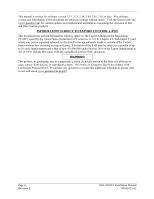
913.397.8200 Aviation Panel-Mount Technical Support Line (Toll Free) 1.888.606.5482 www.garmin.com Garmin (Europe) Ltd. Unit 5, The Remove XM antenna installation data and added GA 55A and GA 57 antenna references. ECO # -----28645 29512 32449 33407 38688 GDL 69/69A Installation Manual 190 - Garmin GDL 69/69A | Installation Manual - Page 4
provided in accordance with California's Proposition 65. If you have any questions or would like additional information, please refer to our web site at www.garmin.com/prop65. Page iv Revision E GDL 69/69A Installation Manual 190-00355-02 - Garmin GDL 69/69A | Installation Manual - Page 5
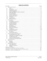
7.2 Equipment Calibration...7-1 7.3 Cleaning ...7-1 APPENDIX A - STC DATA...A-1 APPENDIX B - ENVIRONMENT QUALIFICATION FORM B-1 APPENDIX C - CONSTRUCTION AND VALIDATION OF STRUCTURES C-1 APPENDIX D - INSTALLATION DRAWINGS D-1 GDL 69/69A Installation Manual 190-00355-02 Page v Revision E - Garmin GDL 69/69A | Installation Manual - Page 6
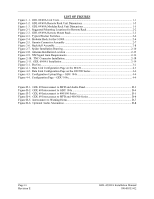
Figure 2-7. Spider Installation Drawing 2-10 Figure 2-8. Antenna Installation Location 2-13 Figure 2-9. XM Signal Gain Requirements 2-14 Figure 2-10. TNC Connector Installation 2-18 Figure 2-11. GDL 69/69A Installation 2-19 Figure 3-1. Pin Out...3-1 Figure 4-1. Data Link Configuration Page on - Garmin GDL 69/69A | Installation Manual - Page 7
2-7. XM Gain/Loss Component Calculation 2-15 Table 2-8. Unit Weights ...2-17 Table 3-1. Pin Out List...3-1 Table 5-1. Troubleshooting Guide ...5-1 Table C-1. Static Test Load (GDL 69 with Remote Rack C-1 Table C-2. Static Test Load (GDL 69A with Remote Rack C-1 GDL 69/69A Installation Manual 190 - Garmin GDL 69/69A | Installation Manual - Page 8
the Garmin Dealer Resource web site at www.garmin.com using their Garmin-provided user name and password. Mod Level 1 Service Bulletin No. - - - - Service Bulletin Date - - - - Purpose Of Modification Mod 1 unit identical to no mod unit Page viii Revision E GDL 69/69A Installation Manual 190 - Garmin GDL 69/69A | Installation Manual - Page 9
in the cabin. The GDL 69A is also interfaced to a Garmin audio panel for amplification and distribution of the audio signal. The XM Satellite Radio antenna receives the XM Satellite Radio data signal and passes it to the GDL 69/69A. GDL 69/69A Installation Manual 190-00355-02 Page 1-1 Revision - Garmin GDL 69/69A | Installation Manual - Page 10
Garmin Garmin Software Version (Or later FAA approved version) Ver. 5.5 4.01 5.00 5.00 4.04 4.04 4.04 4.04 4.04 5.04 5.04 5.04 N/A N/A N/A N/A N/A N/A N/A O R * 400/500 series units must use Pilot Guide Addendum 190-00140-13 Revision D, or later. 400/500 series units may be connected to a GDL 69A - Garmin GDL 69/69A | Installation Manual - Page 11
titles, and coast-to-coast coverage. XM features digital quality audio. Subscriptions to XM Satellite Radio weather and audio entertainment services are required before the GDL 69/69A can be activated for the first use. Refer to Section 4.5 for instructions for activating your unit. NOTE It is - Garmin GDL 69/69A | Installation Manual - Page 12
General Description 1.8 Technical Specifications The GDL 69/69A and GA 55/GA55A XM antenna are PMA approved and there is no applicable TSO. The GA 57 GPS/WAAS - XM antenna is TSO authorized under TSO-c144. It is the responsibility of those desiring to install this equipment either on or within a - Garmin GDL 69/69A | Installation Manual - Page 13
90 175.3 TYP 7.26 184.4 6.30 160.0 3.00 76.2 ANTENNA J691 .60 15.2 .36 9.1 TYP .48 12.2 TYP 4.30 109.2 7.65 194.3 8.73 221.8 .48 12.2 TYP .36 9.1 TYP 4X .38 9.6 4X 3.73 94.7 Figure 1-3. GDL 69/69A Modular Rack Unit Dimensions GDL 69/69A Installation Manual 190-00355-02 Page 1-5 Revision E - Garmin GDL 69/69A | Installation Manual - Page 14
XM Antenna Specifications Frequency Range Gain Noise Figure Nominal Output Impedance Supply Voltage Supply Current Operating Temperature Range Output Connector 2332.5 to 2345 MHz 25 ± 2 dB - Garmin GDL 69/69A | Installation Manual - Page 15
Garmin Optional Displays GDU 1040 Installation Manual GA 55A, GA 56A and GA 57 Antenna Installation Manual XM™ Satellite Radio Activation Instructions MX20 Installation Manual SL15 Audio Panel Installation Manual SL10 Audio Panel Installation Manual 1.10 Certification The GDL 69 and GDL 69A XM - Garmin GDL 69/69A | Installation Manual - Page 16
Inc. 1200 East 151st Street Olathe, Kansas 66062, U.S.A. Phone: 913/397.8200 FAX: 913/397.0836 Garmin (Europe) Ltd. Unit 5, The Quadrangle, Abbey Park Industrial Estate Romsey, SO51 9DL, U.K. Phone: 44/1794.519944 FAX: 44/1794.519222 Page 1-8 Revision E GDL 69/69A Installation Manual 190-00355-02 - Garmin GDL 69/69A | Installation Manual - Page 17
337. 2.3 Installation Materials 2.3.1 Configurations Available Each of the GDL 69 and 69A can be ordered in different kits, each of which may contain components listed in the following table. Table 2-1. Kit Contents Description GDL 69 XM Weather Data Receiver GDL 69A XM Weather/Audio Data Receiver - Garmin GDL 69/69A | Installation Manual - Page 18
the GDL 69/69A near sources that produce high levels of heat. The GDL 69/69A has two mounting rack options available, the remote rack and the modular rack for use with the G1000 system. Figure 2-1. Suggested Mounting Locations for Remote Rack Page 2-2 Revision E GDL 69/69A Installation Manual 190 - Garmin GDL 69/69A | Installation Manual - Page 19
or raising and lowering the channels at the same time. Wire used for discrete switches should be 24 AWG (MIL Spec M22759) and should be routed as appropriate, avoiding kinking or sharp bends. Figure 2-3 shows typical rocker switches. GDL 69/69A Installation Manual 190-00355-02 Page 2-3 Revision E - Garmin GDL 69/69A | Installation Manual - Page 20
KIT 2 115-00657-00 2 PLCS MAY ALTERNATELY USE P/N 115-00511-00 (PART OF KIT 011-01148-00) 3. PART OF 011-00997-00 CONNECTOR KIT 4. APPLY THREAD LOCKING COMPOUND TO ALL THREADED FASTENERS. Figure 2-4. Modular Rack for the G1000 Page 2-4 Revision E GDL 69/69A Installation Manual 190-00355-02 - Garmin GDL 69/69A | Installation Manual - Page 21
wiring could cause component damage. Table 2-2. Pin Contact Part Numbers Wire Gauge Garmin P/N Military P/N AMP Positronic ITT Cannon 78 pin connectors (P691) 22-28 AWG 336-00021-00 M39029/58-360 204370-2 MC8522D 030-2042-000 GDL 69/69A Installation Manual 190-00355-02 Page 2-5 Revision E - Garmin GDL 69/69A | Installation Manual - Page 22
grounds to be made to the backshell housing. Installation details provided in Section 2.5.5. 5. Strain Relief Tab: Provides strength and support to wiring bundles. 6. Backshell Lid: Provides easy access when servicing connector. Page 2-6 Revision E GDL 69/69A Installation Manual 190-00355-02 - Garmin GDL 69/69A | Installation Manual - Page 23
Table 2-4. Garmin Connector Assembly Garmin Part Number 1 125-00085-00 1 012-00605-00 1 330-00185-78 1 320-00212-00 1 115-00499-03 1 115-00500-04 2 211-63234-06 3 211-60234-10 2 211-63234-08 8 2 1 3 5 4 9 Figure 2-5. Garmin Connector Assembly GDL 69/69A Installation Manual - Garmin GDL 69/69A | Installation Manual - Page 24
conductor wire harness (3) into the connector on the PCB Board (1). 5. Insert into the backshell (6) recess, PCB Board (1) with pad (2) in position. 6. Attach cover (7) to backshell (6) using screws (8). Page 2-8 Revision E Figure 2-6. Backshell Assembly GDL 69/69A Installation Manual 190-00355-02 - Garmin GDL 69/69A | Installation Manual - Page 25
w/NYL Qty. Included Garmin Part Number/MIL Spec 0 011-00950-( ) 011-00980-00 1 or 011-00980-01 0 Parts used depend on method chosen 0 Reference Interconnect Diagrams 0 336-00021-00 0 MS25036-152 0 011-00950-( ) 0 211-60234-10 GDL 69/69A Installation Manual 190-00355-02 Page - Garmin GDL 69/69A | Installation Manual - Page 26
tied back and dressed with shrink tubing. 7. Wrap the cable bundle with Silicone Fusion Tape (Garmin P/N: 249-00114-00 or a similar version) at the point where the backshell strain relief (10) and cast housing (1) contacts the cable Page 2-10 Revision E GDL 69/69A Installation Manual 190-00355-02 - Garmin GDL 69/69A | Installation Manual - Page 27
-0-0-N (62111231-0-0-N for the switch used for muting). Since the input signals are active-lo it is permissible to use multiple switches for each function. The would allow volume and channel control to be available at each passenger station. GDL 69/69A Installation Manual 190-00355-02 Page 2-11 - Garmin GDL 69/69A | Installation Manual - Page 28
by Garmin. Other antennas may be acceptable but their installation is not covered by this manual and is outside the scope of the data approved in the GDL 69/69A STC. There are several critical factors to take into consideration before installing an antenna for a satellite communications - Garmin GDL 69/69A | Installation Manual - Page 29
Installation Procedure Figure 2-8. Antenna Installation Location GDL 69/69A Installation Manual 190-00355-02 Page 2-13 Revision E - Garmin GDL 69/69A | Installation Manual - Page 30
Requirements The XM Radio Receiver used in the GDL 69/69A has a system signal requirement of 20dB +/- 1dB gain from the input of the antenna to the input of the XM receiver internal to the GDL 69/69A. To insure the proper operation and optimum performance of the GDL 69/69A, the installation must - Garmin GDL 69/69A | Installation Manual - Page 31
Installation Procedure Table 2-7. XM Gain/Loss Component Calculation Antenna Gain (1) + Cable Loss (2) (3) - GDL 69/69A Gain/Loss (4) +6dB > x > -4dB Total Gain Antenna/Receiver +/= 20 dB Note: (1) Garmin GA 55, GA 55A, GA 57 XM antenna typical gain 25 dB. For antenna gain for other antennas, - Garmin GDL 69/69A | Installation Manual - Page 32
, one end of the coaxial run can be terminated prior to installation. 3. With the GDL 69/69A receiver and antenna installed, route and clamp the coaxial cable in position. Secure cable in accordance with AC 43.13-1B, Chapter 11. Page 2-16 Revision E GDL 69/69A Installation Manual 190-00355-02 - Garmin GDL 69/69A | Installation Manual - Page 33
An electrical load analysis should be completed on each aircraft prior to installation in accordance with AC 43.13-1B, Chapter 11 and recorded on FAA Form 337. Use the following values for computation: GDL 69 Unit Status Off On GDL 69A Max Current @ 28 VDC 0.01 A 0.28 A Max Current @ 14 VDC 0.01 - Garmin GDL 69/69A | Installation Manual - Page 34
inserting the unit into the mount rack, visually note that the Cam Head (2) remains seated in the slot of the Locking Plate (3). Page 2-18 Revision E GDL 69/69A Installation Manual 190-00355-02 - Garmin GDL 69/69A | Installation Manual - Page 35
Locking Lever Handle (1) Locking Lever Handle Securing Screw (4) GDL 69/69A 011-00986-00/011-00987-00 GDL 69/69A Remote Mount Rack 115-00658-00 Figure 2-11. GDL 69/69A Installation CAUTION Do not use excessive force when inserting the GDL 69/69A into the rack. This may cause damage to occur to - Garmin GDL 69/69A | Installation Manual - Page 36
Installation Procedure This Page Intentionally Left Blank Page 2-20 Revision E GDL 69/69A Installation Manual 190-00355-02 - Garmin GDL 69/69A | Installation Manual - Page 37
RS-232 In 1 RS-232 Out 1 Data Link System ID Program 1 Data Link System ID Program 2 Signal Ground Spare Signal Use Only Out For Factory Use Only In In ------Out GDL 69A Only Out GDL 69A Only Out GDL 69A Only -Out In In Out Out In In Out Out In In Out Out -- In GDL 69/69A Installation Manual - Garmin GDL 69/69A | Installation Manual - Page 38
Out -- GDL 69A Only -- GDL 69A Only -- GDL 69A Only -- GDL 69A Only -- GDL 69A Only -- GDL 69A Only In In In For factory use only In In In In In --In In Note 1: Line Out Audio is not supported in GDL 69A with software version prior to 3.00. Page 3-2 Revision E GDL 69/69A Installation Manual 190 - Garmin GDL 69/69A | Installation Manual - Page 39
information. The configuration module is not used when installed with GDU 104x series units. The configuration module does not store XM Satellite Radio subscription information. When a new GDL 69/69A is installed in the aircraft, contact XM Satellite Radio to update the radio IDs on the current - Garmin GDL 69/69A | Installation Manual - Page 40
up to a connection speed of 10 Mb/s. PORT 1 is used to transmit weather data to the display. The other three ports are not supported. PORT 1 P691-22 Ethernet Receiver input Ch1-B P691-23 Ch4-B P691-59 Ethernet Receiver output Ch4-A Page 3-4 Revision E GDL 69/69A Installation Manual 190-00355-02 - Garmin GDL 69/69A | Installation Manual - Page 41
Section 6.2 for requirements on use of suppression inputs. P691-17 Audio Out Lo. This is the common ground for the audio output P691-18 Audio Out Right. This is the right channel audio P691-19 Audio Out Left. This is the left channel audio GDL 69/69A Installation Manual 190-00355-02 Page - Garmin GDL 69/69A | Installation Manual - Page 42
GDL 69/69A. Use of these pins may result in unintended behavior. P691-12 P691-14 P691-15 P691-16 P691-34 P691-36 P691-38 P691-41 P691-42 P691-43 P691-44 P691-45 P691-46 P691-47 P691-48 P691-49 P691-50 P691-51 P691-55 P691-76 Page 3-6 Revision E GDL 69/69A Installation Manual - Garmin GDL 69/69A | Installation Manual - Page 43
configuration initialization procedure is completed. 4.2.1 Configuration Module Procedure for Installation with MX20 Refer to the latest revision of the MX20 Installation Manual (Garmin AT Part Number 560-1025-( )) for instructions. GDL 69/69A Installation Manual 190-00355-02 Page 4-1 Revision E - Garmin GDL 69/69A | Installation Manual - Page 44
GDL 69/69A when using the 400/500 Series as the control and display unit: 1. Power up the 400/500 in Configuration Mode (refer to the 400/500 Install Manual for instructions) 2. Go to GDL in the SECTION field will be displayed. 6. Using the FMS knob, highlight 'GDL69' in the FILE LIST field. 7. Press - Garmin GDL 69/69A | Installation Manual - Page 45
and Connection Power up the GDL 69/69A. View the data link status on the display/control device to verify XM signals are being received. Refer to the MX20 installation manual or the 400/500 Series Pilot's Guide Addendum for instructions on how to access the data link status page on those units - Garmin GDL 69/69A | Installation Manual - Page 46
System Configuration/Checkout Figure 4-2. Data Link Configuration Page on the 400/500 Series (500 Series shown, 400 Series screen is similar) Figure 4-3. Configuration Upload Page - GDU 104x Page 4-4 Revision E Figure 4-4. Configuration Page - GDU 104x GDL 69/69A Installation Manual 190-00355-02 - Garmin GDL 69/69A | Installation Manual - Page 47
performed. 4.5 Activation with XM Satellite Radio Before the GDL 69/69A can be used, the unit has to be activated by XM Satellite Radio and services have to be subscribed to XM Satellite Radio Corporation. Reference latest revision of 190-00355-04. GDL 69/69A Installation Manual 190-00355-02 Page - Garmin GDL 69/69A | Installation Manual - Page 48
System Configuration/Checkout This Page Intentionally Left Blank Page 4-6 Revision E GDL 69/69A Installation Manual 190-00355-02 - Garmin GDL 69/69A | Installation Manual - Page 49
5 TROUBLESHOOTING Table 5-1. Troubleshooting Guide Problem No communication with GDL 69/69A. Action • Check power wiring and pin out. • Verify correct communication port setting on display/control device. No or low-quality XM signal • Ensure the XM antenna has an unobstructed view of satellite - Garmin GDL 69/69A | Installation Manual - Page 50
Troubleshooting This Page Intentionally Left Blank Page 5-2 Revision E GDL 69/69A Installation Manual 190-00355-02 - Garmin GDL 69/69A | Installation Manual - Page 51
of the GDL 69/69A STC. Any higher priority audio cautions or alerts, such as the stall warning or gear warning, must disable XM audio to crew locations by muting the GDL 69A XM audio with the use of the audio suppression discrete inputs on the GDL 69A. 6.2 Installation The GDL 69A XM Satellite Radio - Garmin GDL 69/69A | Installation Manual - Page 52
Limitations This Page Intentionally Left Blank Page 6-2 Revision E GDL 69/69A Installation Manual 190-00355-02 - Garmin GDL 69/69A | Installation Manual - Page 53
use of audio suppression inputs, each installed input must be verified for proper operation on an annual basis. 7.2 Equipment Calibration No scheduled servicing tasks or internal manual adjustments are required on the GDL 69/69A. 7.3 Cleaning The GDL 69/69A does not require regular cleaning. GDL 69 - Garmin GDL 69/69A | Installation Manual - Page 54
Periodic Maintenance This Page Intentionally Left Blank Page 7-2 Revision E GDL 69/69A Installation Manual 190-00355-02 - Garmin GDL 69/69A | Installation Manual - Page 55
GDL 69A XM Satellite Radio is approved for installation on all aircraft listed on the AML following installation instructions and limitations described in this GDL 69/69A Installation Manual. The AML is attached to the STC and may be downloaded from the Garmin web site at www.garmin.com. GDL 69/69A - Garmin GDL 69/69A | Installation Manual - Page 56
STC Data This Page Intentionally Left Blank Page A-2 Revision E GDL 69/69A Installation Manual 190-00355-02 - Garmin GDL 69/69A | Installation Manual - Page 57
http://www.garmin.com for the latest Environmental Qualification Forms. Refer to the table below for the specific Qualification Form number. Model GDL 69/69A GA 55 GA 55A GA 57 Qualification Form Number 005-00217-33 005-00233-00 005-00240-00 005-00240-00 GDL 69/69A Installation Manual 190-00355 - Garmin GDL 69/69A | Installation Manual - Page 58
Environmental Qualification Form This Page Intentionally Left Blank Page B-2 Revision E GDL 69/69A Installation Manual 190-00355-02 - Garmin GDL 69/69A | Installation Manual - Page 59
capable of supporting the required loads. The GDL69/69A installation must be use a calibrated force gauge at the location of the center of gravity when the unit is mounted. 4. Verify there is no damage or permanent deformation of the structure after 3 seconds. GDL 69/69A Installation Manual - Garmin GDL 69/69A | Installation Manual - Page 60
found in Tables C-1 and C-2. 7. Examine the support structure carefully. If there has been damage or permanent GDL 69/69A equipment rack may be permanently mounted on it. Figure C-1. Upward Static Load Test Figure C-2. Forward Static Load Test Page C-2 Revision E GDL 69/69A Installation Manual - Garmin GDL 69/69A | Installation Manual - Page 61
Appendix D - Installation Drawings Installation Drawings GDL 69/69A Installation Manual 190-00355-02 Page D-1 Revision E - Garmin GDL 69/69A | Installation Manual - Page 62
Installation Drawings This Page Intentionally Left Blank Page D-2 Revision E GDL 69/69A Installation Manual 190-00355-02 - Garmin GDL 69/69A | Installation Manual - Page 63
Antenna Mounting Diagrams Figure D-1. GDL 69 Interconnect to MFD and Audio Panel GDL 69/69A Installation Manual 190-00355-02 Page D-3 Revision E - Garmin GDL 69/69A | Installation Manual - Page 64
Installation Drawings Figure D-2. GDL 69 Interconnect to GDU 104x Page D-4 Revision E GDL 69/69A Installation Manual 190-00355-02 - Garmin GDL 69/69A | Installation Manual - Page 65
Installation Drawings Figure D-3. GDL 69 Interconnect to 400/500 Series GDL 69/69A Installation Manual 190-00355-02 Page D-5 Revision E - Garmin GDL 69/69A | Installation Manual - Page 66
Installation Drawings Figure D-4. GDL 69 Interconnect to MFD and 400/500 Series Page D-6 Revision E GDL 69/69A Installation Manual 190-00355-02 - Garmin GDL 69/69A | Installation Manual - Page 67
Installation Drawings Figure D-5. Interconnect to Warning Horns GDL 69/69A Installation Manual 190-00355-02 Page D-7 Revision E - Garmin GDL 69/69A | Installation Manual - Page 68
Installation Drawings Page D-8 Revision E Figure D-6. Optional Audio Attenuation GDL 69/69A Installation Manual 190-00355-02 - Garmin GDL 69/69A | Installation Manual - Page 69
- Garmin GDL 69/69A | Installation Manual - Page 70
-
 1
1 -
 2
2 -
 3
3 -
 4
4 -
 5
5 -
 6
6 -
 7
7 -
8
-
9
-
10
-
11
-
12
-
13
-
14
-
15
-
16
-
17
-
18
-
19
-
20
-
21
-
22
-
23
-
24
-
25
-
26
-
27
-
28
-
29
-
30
-
31
-
32
-
33
-
34
-
35
-
36
-
37
-
38
-
39
-
40
-
41
-
42
-
43
-
44
-
45
-
46
-
47
-
48
-
49
-
50
-
51
-
52
-
53
-
54
-
55
-
56
-
57
-
58
-
59
-
60
-
61
-
62
-
63
-
64
-
65
-
66
-
67
-
68
-
69
-
70
 |
 |
190-00355-02
June 2006
Revision E
GDL 69/69A
Installation Manual