Garmin GDL 69/69A Installation Manual - Page 27
D-1 and D-2
 |
View all Garmin GDL 69/69A manuals
Add to My Manuals
Save this manual to your list of manuals |
Page 27 highlights
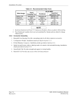
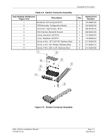
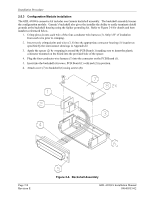
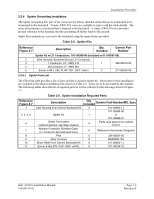
Installation Procedure bundle. Separation of the bundle into two smaller bundles, wrapped individually, may make installation of the strain relief easier. 8. Place the smooth side of the backshell strain relief (10) across the cable bundle and secure using the three screws (11). WARNING Placing the strain relief grooved side across the cable bundle may cause damage to wires. 9. Attach the Spider terminal (2) to the backshell (1) by inserting the two screws (5) into the tapped holes on the backshell (1). 10. Attach a ring terminal (9) to the AWG #16 wire (3) length 24" and terminate to ground. The ground connection can be made using either the closest aircraft ground or with tabs on racks. Trimming of this wire to the shortest practical length before attaching the ring terminal is recommended to reduce the effects of noise and interference. Do not extend this wire's length. 2.5.6 Audio Suppression XM Audio Entertainment to crew locations may require audio suppression to comply with the STC Limitations. Determine the activation state for each horn installed in the aircraft (aircraft power signifying active high or ground signifying active low) by using one of the following methods: • Find the horn and compare the installation with Figure D-5. • Activate the horn per the method described in the aircraft's maintenance manual. (For the gear horn, this may require having the aircraft raised on jacks). • With a multimeter, determine which horn contact changes state with the activation signal and if the active state is high or low. Wire the appropriate audio suppression input (high or low) in accordance with Figure D-5. 2.5.7 Remote Discrete Switches (Optional) If XM audio entertainment is installed in the aircraft, optional functional switches may be installed as desired. The functions of the switches must include the ability to mute the audio, adjust the volume and channels. It may be incorporated as desired depending on the installation. Figure D-1 and Figure D-2 detail the wiring for the optional discrete switches. A common aircraft ground signal may be used for each switch. It is recommended to use a rocker type switch for channel and volume control. Using a rocker type switch will prevent inadvertently raising and lowering the channel at the same time as well as the volume. An acceptable switch for this installation of the remote discrete switches is Carlingswitch P/N 62111281-0-0-N (62111231-0-0-N for the switch used for muting). Since the input signals are active-lo it is permissible to use multiple switches for each function. The would allow volume and channel control to be available at each passenger station. GDL 69/69A Installation Manual 190-00355-02 Page 2-11 Revision E
-
 1
1 -
2
-
3
-
4
-
5
-
6
-
7
-
8
-
9
-
10
-
11
-
12
-
13
-
14
-
15
-
16
-
17
-
18
-
19
-
20
-
21
-
 22
22 -
 23
23 -
 24
24 -
 25
25 -
 26
26 -
 27
27 -
 28
28 -
 29
29 -
 30
30 -
 31
31 -
 32
32 -
33
-
34
-
35
-
36
-
37
-
38
-
39
-
40
-
41
-
42
-
43
-
44
-
45
-
46
-
47
-
48
-
49
-
50
-
51
-
52
-
53
-
54
-
55
-
56
-
57
-
58
-
59
-
60
-
61
-
62
-
63
-
64
-
65
-
66
-
67
-
68
-
69
-
70
 |
 |
