Garmin GDL 69/69A Installation Manual - Page 25
Revision E
 |
View all Garmin GDL 69/69A manuals
Add to My Manuals
Save this manual to your list of manuals |
Page 25 highlights
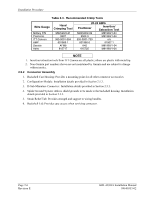
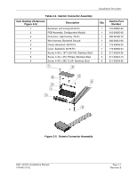
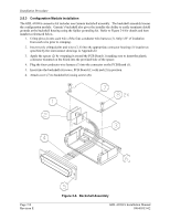
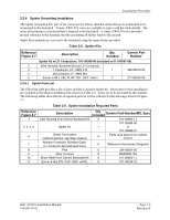
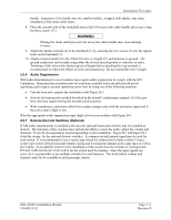
Installation Procedure 2.5.4 Spider Grounding Installation The Spider Grounding Kit, part of the connector kit, allows shielded cables that go to a backshell to be terminated to the backshell. Twenty AWG #24 wires are available to splice with the cable shields. The wires all terminate to a terminal that is fastened to the backshell. A single AWG #16 wire provides ground reference to the terminal, thereby grounding all Spider leads to the aircraft. Spider Kit terminals are screwed to the backshell using the tapped holes provided. Table 2-5. Spider Kits Reference Figure 2-7 Description Qty. Included Garmin Part Number Spider Kit w/ 21 Conductors: 011-00980-00 (Included in 011-00997-00) 2 Wire Harness, Backshell Ground, 21 Conductor 3 1 Conductor, 24", AWG #16 1 4 20 Conductor, 6", AWG #24 5 Screw, 4-40 x .250, FLHP 100°, SS/P, Nylon 2 320-00212-00 211-63234-08 2.5.4.1 Spider Parts List The following table provides a list of parts needed to install a Spider kit. Most parts for this installation are included in the Spider installation kits shown in Table 2-5. Some are to be provided by the installer. The following tables show the list of required parts as well as callouts for the drawings shown in Figure 2-7. Table 2-6. Spider Installation Required Parts Reference Figure 2-7 1 2, 3, 4, 5 6 7 8 9 10 11 Description Cast Housing from Garmin Backshell Kit Spider Kit Shield Termination (method optional, see Step 3 below) Multiple-Conductor Shielded Cable (2 -conductor demonstrated here) Pins Ring Terminal Strain Relief from Garmin Backshell Kit Screw, 4-40x.375, PHP, SS/P, w/NYL Qty. Included Garmin Part Number/MIL Spec 0 011-00950-( ) 011-00980-00 1 or 011-00980-01 0 Parts used depend on method chosen 0 Reference Interconnect Diagrams 0 336-00021-00 0 MS25036-152 0 011-00950-( ) 0 211-60234-10 GDL 69/69A Installation Manual 190-00355-02 Page 2-9 Revision E
-
 1
1 -
2
-
3
-
4
-
5
-
6
-
7
-
8
-
9
-
10
-
11
-
12
-
13
-
14
-
15
-
16
-
17
-
18
-
19
-
 20
20 -
 21
21 -
 22
22 -
 23
23 -
 24
24 -
 25
25 -
 26
26 -
 27
27 -
 28
28 -
 29
29 -
 30
30 -
31
-
32
-
33
-
34
-
35
-
36
-
37
-
38
-
39
-
40
-
41
-
42
-
43
-
44
-
45
-
46
-
47
-
48
-
49
-
50
-
51
-
52
-
53
-
54
-
55
-
56
-
57
-
58
-
59
-
60
-
61
-
62
-
63
-
64
-
65
-
66
-
67
-
68
-
69
-
70
 |
 |
