Garmin GDL 69/69A Installation Manual - Page 28
XM Antenna
 |
View all Garmin GDL 69/69A manuals
Add to My Manuals
Save this manual to your list of manuals |
Page 28 highlights
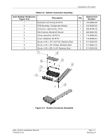
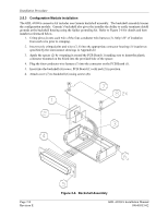
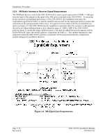
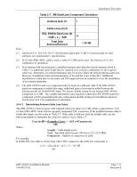
Installation Procedure 2.6 XM Antenna For use with the GDL 69/69A, the GA 55, GA 55A, and GA 57 antennas are an XM Satellite Radio antenna operating within a frequency range of 2332-2345 MHz for general aviation. NOTE Depending on specific installations, the installer may want to use a different make/model of XM Satellite Radio antenna. (An alternate antenna may be used providing it meets the minimum requirements shown in Table 1-6). It is the installer's responsibility to ensure that their choice of antenna meets FAA certification standards according to the specific installation. This installation manual discusses only the antennas listed in Table 1-5, which is used during STC certification by Garmin. Other antennas may be acceptable but their installation is not covered by this manual and is outside the scope of the data approved in the GDL 69/69A STC. There are several critical factors to take into consideration before installing an antenna for a satellite communications system. These factors are addressed in the following sections. 2.6.1 Antenna Mounting For installation mounting of the XM antenna listed in Table 1-5, use Garmin GA Antenna AML STC. Verify aircraft model is listed on the AML and follow limitations defined in that STC data. 2.6.2 Antenna Grounding NOTE Improper grounding of the antenna is typically the primary cause of reduced signal reception quality. It is very important to have good conductivity between the coaxial shield and the ground plane. This is ensured when all the fasteners properly ground the antenna base to the skin of the aircraft. The resistance between the antenna and the skin of the aircraft should be less than 10 milliohms. 2.6.3 XM Antenna Location As with any antenna installation, keep the following points in mind: 1. The XM Satellite signal is a line-of-sight signal. Locating antennas too close to obstructions such as the vertical stabilizer will limit the reception of the satellite signal. 2. Maintain about three feet from heater, ignition, autopilot, and other control surface actuators and motors. Maintain about five feet from fluorescent lamps, related ballast, air conditioners, blowers, strobe lights and power supplies. 3. The minimum distances to be observed when selecting an antenna location are as follows: • 1.25 inches from any passive (receive only) antenna such as a GPS or another XM. • 5 inches from a VHF active antenna such as COM or ACARS. • 5 inches from an active radar altimeter (4 GHz). • 12 inches from a UHF / Microwave transmitting antenna such as a transponder, DME, active TCAS, UAT, SATCOM, or Flitephone. 4. The XM antenna must be mounted on top of the aircraft for greatest satellite visibility. For best performance, select a location with an unobstructed view of the sky above the aircraft when in level flight. Location of communication antennas too close to the XM antenna may not only degrade the transmission through reflection, but can also absorb and re-radiate the transmission causing a condition similar to having two COM antennas located in close proximity to each other. Page 2-12 Revision E GDL 69/69A Installation Manual 190-00355-02
-
 1
1 -
2
-
3
-
4
-
5
-
6
-
7
-
8
-
9
-
10
-
11
-
12
-
13
-
14
-
15
-
16
-
17
-
18
-
19
-
20
-
21
-
22
-
 23
23 -
 24
24 -
 25
25 -
 26
26 -
 27
27 -
 28
28 -
 29
29 -
 30
30 -
 31
31 -
 32
32 -
 33
33 -
34
-
35
-
36
-
37
-
38
-
39
-
40
-
41
-
42
-
43
-
44
-
45
-
46
-
47
-
48
-
49
-
50
-
51
-
52
-
53
-
54
-
55
-
56
-
57
-
58
-
59
-
60
-
61
-
62
-
63
-
64
-
65
-
66
-
67
-
68
-
69
-
70
 |
 |
