Garmin GDL 69/69A Installation Manual - Page 20
Typical Rocker Switches, Modular Rack for the G1000
 |
View all Garmin GDL 69/69A manuals
Add to My Manuals
Save this manual to your list of manuals |
Page 20 highlights
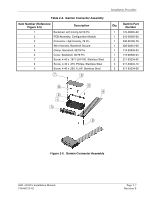
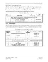
Installation Procedure Channel Volume Mute Figure 2-3. Typical Rocker Switches 1 330-00053-02 125-00097-00 1 1 212-00022-00 PART OF 330-00053-02 011-00950-04 3 211-63207-10 8 PLCS 2 330-00185-78 3 125-00059-04 1 211-63234-10 1 3 PLCS 211-63234-12 2 PLCS 3 115-00411-00 NOTES: 1. PART OF 011-00796-35 BACK PLATE ASSEMBLY 2. PART OF 011-00915-00 NUT PLATE KIT 2 115-00657-00 2 PLCS MAY ALTERNATELY USE P/N 115-00511-00 (PART OF KIT 011-01148-00) 3. PART OF 011-00997-00 CONNECTOR KIT 4. APPLY THREAD LOCKING COMPOUND TO ALL THREADED FASTENERS. Figure 2-4. Modular Rack for the G1000 Page 2-4 Revision E GDL 69/69A Installation Manual 190-00355-02
-
 1
1 -
2
-
3
-
4
-
5
-
6
-
7
-
8
-
9
-
10
-
11
-
12
-
13
-
14
-
 15
15 -
 16
16 -
 17
17 -
 18
18 -
 19
19 -
 20
20 -
 21
21 -
 22
22 -
 23
23 -
 24
24 -
 25
25 -
26
-
27
-
28
-
29
-
30
-
31
-
32
-
33
-
34
-
35
-
36
-
37
-
38
-
39
-
40
-
41
-
42
-
43
-
44
-
45
-
46
-
47
-
48
-
49
-
50
-
51
-
52
-
53
-
54
-
55
-
56
-
57
-
58
-
59
-
60
-
61
-
62
-
63
-
64
-
65
-
66
-
67
-
68
-
69
-
70
 |
 |

Installation Procedure
Page 2-4
GDL 69/69A Installation Manual
Revision E
190-00355-02
Channel
Volume
Mute
Figure 2-3.
Typical Rocker Switches
2
MAY ALTERNATELY USE P/N 115-00511-00
(PART OF KIT 011-01148-00)
011-00950-04
330-00185-78
211-63207-10
8 PLCS
2 PLCS
115-00657-00
4.
APPLY THREAD LOCKING COMPOUND TO ALL THREADED FASTENERS.
2.
PART OF 011-00915-00 NUT PLATE KIT
1.
PART OF 011-00796-35 BACK PLATE ASSEMBLY
NOTES:
115-00411-00
125-00059-04
2
1
211-63234-12
212-00022-00
125-00097-00
330-00053-02
1
1
1
PART OF 330-00053-02
3
3
1
211-63234-10
3.
PART OF 011-00997-00 CONNECTOR KIT
3 PLCS
3
2 PLCS
Figure 2-4.
Modular Rack for the G1000