Garmin GDL 69/69A Installation Manual - Page 31
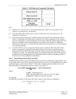
Table 2-7., XM Gain/Loss Component Calculation, Antenna Gain 1, Cable Loss 2 3, GDL 69/69A Gain/Loss
 |
View all Garmin GDL 69/69A manuals
Add to My Manuals
Save this manual to your list of manuals |
Page 31 highlights
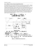
Installation Procedure Table 2-7. XM Gain/Loss Component Calculation Antenna Gain (1) + Cable Loss (2) (3) - GDL 69/69A Gain/Loss (4) +6dB > x > -4dB Total Gain Antenna/Receiver +/= 20 dB Note: (1) Garmin GA 55, GA 55A, GA 57 XM antenna typical gain 25 dB. For antenna gain for other antennas, see manufacturer's specifications. (2) If 12-16ft of RG-400/U cable is used, a value of 4.5dB can be used. See Section 2.6.4.1 for explanation of calculation. (3) If an antenna with increased gain is installed (antenna other than the Garmin antennas listed in Table 1-5), additional cable length may be required to be coiled to compensate for the required cable loss. Alternately, an external attenuator may be used to obtain the desired antenna cable loss. However, installation of the external attenuator is beyond the scope of this STC. Additional manufacturer's data may be necessary and FAA approval may be required to cover the installation of an external attenuator. (4) The GDL 69/69A Gain/Loss component must be between +6dB and -4dB. If the GDL 69/69A gain/loss component is outside this range, additional gain or loss must be added between the antenna and the GLD 69/69A RF input. The factory default setting for the internal GDL 69/69A component is -0.5dB. The variable attenuation value required to attain the GDL 69/69A gain/loss component will be programmed into the configuration module during post installation checkout. See Section 2.6.4.2 for explanation of calculation. 2.6.4.1 Determining Antenna Cable Loss Value The GDL 69/69A is factory preset with a default cable loss value of 4.5 dB, which is equivalent to 12 to 16 feet of RG-400/U cable with two properly terminated TNC connectors. If the installed antenna cable is within this length, use this value in Table 2-7. If the cable is different from the default cable, use the following formula to determine the cable loss value to use in Table 2-7. Loss in dB = (Length x Loss) + (0.5 x #Connectors) 100 Where: Length - Cable length in feet Loss - Specified cable loss per 100 feet at 2332-2345 MHz Connectors - Number of connectors on cable For example: If an RG-400 coax cable is 10 feet long with 2 TNC connectors, the cable loss component is Loss = (10 x 26.1) + (0.5 x 2) = 3.61 dB 100 GDL 69/69A Installation Manual 190-00355-02 Page 2-15 Revision E
-
 1
1 -
2
-
3
-
4
-
5
-
6
-
7
-
8
-
9
-
10
-
11
-
12
-
13
-
14
-
15
-
16
-
17
-
18
-
19
-
20
-
21
-
22
-
23
-
24
-
25
-
 26
26 -
 27
27 -
 28
28 -
 29
29 -
 30
30 -
 31
31 -
 32
32 -
 33
33 -
 34
34 -
 35
35 -
 36
36 -
37
-
38
-
39
-
40
-
41
-
42
-
43
-
44
-
45
-
46
-
47
-
48
-
49
-
50
-
51
-
52
-
53
-
54
-
55
-
56
-
57
-
58
-
59
-
60
-
61
-
62
-
63
-
64
-
65
-
66
-
67
-
68
-
69
-
70
 |
 |
