Garmin GDL 69/69A Installation Manual - Page 34
Cooling Air, 10 Installing/Inserting Unit
 |
View all Garmin GDL 69/69A manuals
Add to My Manuals
Save this manual to your list of manuals |
Page 34 highlights
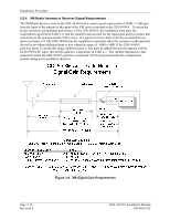
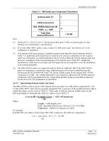
Installation Procedure = Figure 2-10. TNC Connector Installation 2.9 Cooling Air The GDL 69/69A units do not require cooling air and do not generate an excessive amount of heat during typical operations; however the thermal characteristics of the installation should always be assessed. An undesirable thermal condition could be created due to the unit's own internal power dissipation combined with restricted ventilation, or due to heat generated by adjacent equipment. Limiting thermal build up, by means of fan or natural convection is always a good practice and recommended to increase the product life. 2.10 Installing/Inserting Unit For final installation and assembly, refer to the outline and installation drawings shown in Figure 2-2 or Figure 2-4 of this manual. The two installation configurations available are the G1000 modular rack or remote mount. For both configurations, insert the GDL 69/69A into the rack, noting proper orientation as shown on the installation drawing in Figure 2-2 or Figure 2-4. NOTE The following steps are for the remote mounting rack which is illustrated in Figure 2-11. The steps are identical for the modular rack. 1. Loosen and remove the Locking Lever Handle Securing Screw (4). Then, lift up on the end of the Locking Lever Handle (1). 2. Slide the GDL 69/69A unit into the Mount Rack carefully fitting the Locking Lever Handle Cam Head (2) into the slot of the Locking Plate (3) of the Mount Rack. 3. After fully inserting the unit into the mount rack, visually note that the Cam Head (2) remains seated in the slot of the Locking Plate (3). Page 2-18 Revision E GDL 69/69A Installation Manual 190-00355-02
-
 1
1 -
2
-
3
-
4
-
5
-
6
-
7
-
8
-
9
-
10
-
11
-
12
-
13
-
14
-
15
-
16
-
17
-
18
-
19
-
20
-
21
-
22
-
23
-
24
-
25
-
26
-
27
-
28
-
 29
29 -
 30
30 -
 31
31 -
 32
32 -
 33
33 -
 34
34 -
 35
35 -
 36
36 -
 37
37 -
 38
38 -
 39
39 -
40
-
41
-
42
-
43
-
44
-
45
-
46
-
47
-
48
-
49
-
50
-
51
-
52
-
53
-
54
-
55
-
56
-
57
-
58
-
59
-
60
-
61
-
62
-
63
-
64
-
65
-
66
-
67
-
68
-
69
-
70
 |
 |
