Garmin GDL 69/69A Installation Manual - Page 23
Table 2-4., Garmin Connector Assembly, Item Number Reference, Description, Garmin Part,
 |
View all Garmin GDL 69/69A manuals
Add to My Manuals
Save this manual to your list of manuals |
Page 23 highlights
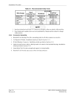
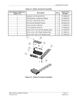
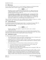
Table 2-4. Garmin Connector Assembly Item Number (Reference Figure 2-5) Description 1 Backshell, with Config 50/78 Pin 2 PCB Assembly, Configuration Module 3 Connector, High Density, 78 Pin 4 Wire Harness, Backshell Ground 5 Clamp, Backshell, 62/78 Pin 6 Cover, Backshell, 50/78 Pin 7 Screw, 4-40 x .187 FLHP100, Stainless Steel 8 Screw, 4-40 x .375, Phillips, Stainless Steel 9 Screw, 4-40 x .250, FLHP, Stainless Steel 7 6 Installation Procedure Qty Garmin Part Number 1 125-00085-00 1 012-00605-00 1 330-00185-78 1 320-00212-00 1 115-00499-03 1 115-00500-04 2 211-63234-06 3 211-60234-10 2 211-63234-08 8 2 1 3 5 4 9 Figure 2-5. Garmin Connector Assembly GDL 69/69A Installation Manual 190-00355-02 Page 2-7 Revision E
-
 1
1 -
2
-
3
-
4
-
5
-
6
-
7
-
8
-
9
-
10
-
11
-
12
-
13
-
14
-
15
-
16
-
17
-
 18
18 -
 19
19 -
 20
20 -
 21
21 -
 22
22 -
 23
23 -
 24
24 -
 25
25 -
 26
26 -
 27
27 -
 28
28 -
29
-
30
-
31
-
32
-
33
-
34
-
35
-
36
-
37
-
38
-
39
-
40
-
41
-
42
-
43
-
44
-
45
-
46
-
47
-
48
-
49
-
50
-
51
-
52
-
53
-
54
-
55
-
56
-
57
-
58
-
59
-
60
-
61
-
62
-
63
-
64
-
65
-
66
-
67
-
68
-
69
-
70
 |
 |

Installation Procedure
GDL 69/69A Installation Manual
Page 2-7
190-00355-02
Revision E
Table 2-4.
Garmin Connector Assembly
Item Number (Reference
Figure 2-5)
Description
Qty
Garmin Part
Number
1
Backshell, with Config 50/78 Pin
1
125-00085-00
2
PCB Assembly, Configuration Module
1
012-00605-00
3
Connector, High Density, 78 Pin
1
330-00185-78
4
Wire Harness, Backshell Ground
1
320-00212-00
5
Clamp, Backshell, 62/78 Pin
1
115-00499-03
6
Cover, Backshell, 50/78 Pin
1
115-00500-04
7
Screw, 4-40 x .187 FLHP100, Stainless Steel
2
211-63234-06
8
Screw, 4-40 x .375, Phillips, Stainless Steel
3
211-60234-10
9
Screw, 4-40 x .250, FLHP, Stainless Steel
2
211-63234-08
7
6
5
4
8
2
1
3
9
Figure 2-5.
Garmin Connector Assembly