Garmin GDL 69/69A Installation Manual - Page 35
Caution
 |
View all Garmin GDL 69/69A manuals
Add to My Manuals
Save this manual to your list of manuals |
Page 35 highlights
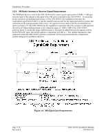
Installation Procedure NOTE When inserting the GDL 69/69A into the Remote Mount Rack, it may be possible for the Pivot Pin (2) to fit between the unit and the mount rack without going into the slot of the Locking Plate (3). If the Cam Head (2) does not seat in the slot of the Locking Plate (3), the unit will not firmly engage with the mount rack and the unit could come loose from the rack. 4. With the unit firmly engaged with the mount rack, lower the Locking Lever Handle (1). Then, insert and tighten the Locking Lever Handle Securing Screw (4) to mechanically secure the unit to the Mount Rack. Locking Plate (3) Locking Lever Handle Cam Head (2) Locking Lever Handle (1) Locking Lever Handle Securing Screw (4) GDL 69/69A 011-00986-00/011-00987-00 GDL 69/69A Remote Mount Rack 115-00658-00 Figure 2-11. GDL 69/69A Installation CAUTION Do not use excessive force when inserting the GDL 69/69A into the rack. This may cause damage to occur to the connectors, unit, and/or unit rack. If heavy resistance is felt during installation, STOP! Remove the GDL 69/69A and identify the source of resistance. The unit is designed with a key and the back plate is designed to float in the unit rack. Check to ensure the rear plate is not bound by the connector harness. GDL 69/69A Installation Manual 190-00355-02 Page 2-19 Revision E
-
 1
1 -
2
-
3
-
4
-
5
-
6
-
7
-
8
-
9
-
10
-
11
-
12
-
13
-
14
-
15
-
16
-
17
-
18
-
19
-
20
-
21
-
22
-
23
-
24
-
25
-
26
-
27
-
28
-
29
-
 30
30 -
 31
31 -
 32
32 -
 33
33 -
 34
34 -
 35
35 -
 36
36 -
 37
37 -
 38
38 -
 39
39 -
 40
40 -
41
-
42
-
43
-
44
-
45
-
46
-
47
-
48
-
49
-
50
-
51
-
52
-
53
-
54
-
55
-
56
-
57
-
58
-
59
-
60
-
61
-
62
-
63
-
64
-
65
-
66
-
67
-
68
-
69
-
70
 |
 |
