Genie ScrewDrive Owner's Manual
Genie ScrewDrive Manual
 |
View all Genie ScrewDrive manuals
Add to My Manuals
Save this manual to your list of manuals |
Genie ScrewDrive manual content summary:
- Genie ScrewDrive | Owner's Manual - Page 1
prior to operation of this Garage Door Operator Safe-T-Beam® Safety Reverse System Must be installed to close door NOTE: Your Residential Operator comes with a Rail Assembly which is standard for up to a 7 foot 6 inch high door. An extension kit for an 8 foot high door is available. For Answers and - Genie ScrewDrive | Owner's Manual - Page 2
® is a universal transceiver (a combined transmitter and receiver), that provides a convenient way to replace up to three hand-held radio-frequency (RF) transmitters used to activate devices such as gate operators, garage door openers, entry door locks, security systems and even home lighting - Genie ScrewDrive | Owner's Manual - Page 3
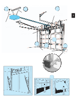
TYPICAL SECTIONAL DOOR INSTALLATION 5 1 TYPICAL SUPPORT BRACKET 2 ADDED HEADER BRACKET MOUNTING BOARD 3 BRACES 36" POWER CORD TO 120V GROUNDED OUTLET EXTENSION SPRING OR TORSION SPRING 4 3 6 3 SAFE-T-BEAM® TYPICAL 1-PIECE DOOR INSTALLATION 7 SECTIONAL DOOR 1-PIECE DOOR - Genie ScrewDrive | Owner's Manual - Page 4
PROGRAMMING REMOTE CONTROLS 29 TRANSMITTER COMPLIANCE STATEMENT 30 IMPORTANT SAFETY INSTRUCTIONS 30 10 MAINTENANCE & TROUBLESHOOTING turns on when door is activated and automatically turns off 4.5 minutes later. Manual Emergency Release Allows the garage door to be opened or closed manually - Genie ScrewDrive | Owner's Manual - Page 5
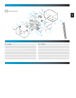
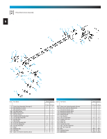
(By Series/Model) B Front Plate Assembly C Light Socket D Motor Parts E Receiver Assembly F Capacitor (By Series/Model) G Opto Wheel H Opto-Luctor Assembly J Sequencer Assembly K Circuit Board Bracket L Transformer Item Part Name M Terminal Strip N No. 8-32 x 1/2" Hex Washer Head Screw P No. 8-32 - Genie ScrewDrive | Owner's Manual - Page 6
Rail Section 3B Middle Rail Section 3C End Rail Section 4 1/4-20 Hex Hd Shoulder Bolt 5 1/4"-20 Hex Flange Nut 6 Carriage Stop 7 Rail Clamps 8 5/16" Hex Shoulder Bolt 9 5/16" Hex Flange Nut 10 Carriage Assembly 11 Collar 12 Retaining Clip 13 Rail Strap 15A Open Limit Switch Assembly (Grey) Parts - Genie ScrewDrive | Owner's Manual - Page 7
[3] 3-Piece Rail & Screw Assembly FOR HELP Screw 41 #8 x 3/8" Hex Head Screw 42 #8 x 3/8" Pan Head Screw 43 Safety & Maintenance Guide 44 Wire Clip 45 Bumper 46 5/16" x 3/4" Hex Head Bolt 47 1/4-20 x 3/4" Self-tapping Screw 48 Mounting Straps 49 Light Lens (Shown on page 5) 50 Remote Control Parts - Genie ScrewDrive | Owner's Manual - Page 8
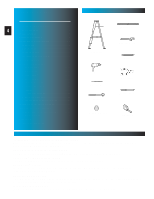
.COM 29 8 35 36 19 31 33 remotes 37 vary by model 38 50 43 NOTE: Accessories vary by model. FASTENERS - Shown full size. See Parts List for description. 4 22 39 1/4" Shoulder bolt w/flange 5 1/4" Flange nut 6 OR Carriage stop (not to scale) 8 5/16" Shoulder bolt w/flange - Genie ScrewDrive | Owner's Manual - Page 9
Operator Model Dealer Name 2. Do Not install Opener on an improperly balanced door. An improperly balanced door may cause severe injury. Repairs and adjustments to cables, spring assemblies, and other hardware must be made by a trained service person using proper tools and instructions - Genie ScrewDrive | Owner's Manual - Page 10
OPEN BLUE PARTS BAG NOTE: 3-piece rail assembly is for doors up to 10 and including 7 feet 6 inches high. An extension for 8 feet doors is available. 1. Set power head so that front panel (with end of shaft and rail attachment flange) is facing up. Fig. 1-1. NOTE: If you have this type Carriage Stop - Genie ScrewDrive | Owner's Manual - Page 11
1-6. 11 • Find arrows stamped into side of rail. Fig. 1-7. • Align rail so arrows point away from power head. • Slide screw toward power head so it sticks out end of rail section about 2 inches. Fig. 1-5 middle rail section end rail section Fig. 1-6 Fig. 1-7 [4] 1/4" Shoulder bolt w/flange - Genie ScrewDrive | Owner's Manual - Page 12
ASSEMBLY • Slide a collar [11] over exposed end of screw on "middle" rail as far as it will go. Fig. 1-8. 12 • Engage "hook" on "middle" rail with "hook" on "first" rail section. Fig. 1-9. • Slide collar toward power head so that it now covers hooks. Fig. 1-10. • Snap a clip [12] onto screw - Genie ScrewDrive | Owner's Manual - Page 13
kit for an 8 feet high door, refer to the instructions carriage stop included with the extension kit now. 7. Attach "end" rail section [3C]. 13 • Attach "end" rail in same way as "middle" rail (step 5). ("End" rail section screw has "hook" on one end only.) 8. Flip power head/rail assembly - Genie ScrewDrive | Owner's Manual - Page 14
ASSEMBLY OPEN GREEN PARTS BAG Screws - Slide cord through hole in emergency release lever (on carriage). - Tie a second knot in this end. Fig. rail back to power head. - Use wire clip [44] to help maintain slack. Fig. 1-20. • "OPEN" limit switch [15A]. - Place "OPEN" limit switch over top of rail - Genie ScrewDrive | Owner's Manual - Page 15
"bend" as it rides on a curved track. 1-PIECE DOORS-consist of one large panel and swivel on large spring-loaded hinges on each side of door. CENTERLINE TYPICAL TRACKLESS garage door CENTERLINE floor TYPICAL TRACK GUIDED garage door 15 1. Determining header bracket location. • Find center of - Genie ScrewDrive | Owner's Manual - Page 16
Finding highest point of travel. • While raising garage door manually, watch top edge of door to see where it reaches its 16 highest door in position by clamping it onto the rail. (A stool, chair, table or any object that can safely support door will also work.) - With door held partly open - Genie ScrewDrive | Owner's Manual - Page 17
with step 5. garage door opening OPEN ORANGE PARTS BAG TYPICAL FINISHED WALL floor Fig. 2-5 5. Mounting preparation. • Hold bracket against wall where final header bracket height crosses centerline. • Make sure flange where rail strap attaches, is on centerline. Fig. 2-6. • Mark screw hole - Genie ScrewDrive | Owner's Manual - Page 18
.COM 7. Attaching rail to header bracket. • Gently set power head on garage floor while leaning rail strap against header feet depending on position of torsion spring(s). Be sure to use a stable support device, such as a ladder. • Slide threaded stud of rail strap through hole in flange of - Genie ScrewDrive | Owner's Manual - Page 19
-1.800.354.3643 OR GENIECOMPANY.COM 8. Mounting power head. • Raise power head and support it high enough that you can manually raise garage 19 door fully open. • Line up power head and rail with center of door. Fig. 2-9. • Keeping power head centered, mount to ceiling: - at proper height - Genie ScrewDrive | Owner's Manual - Page 20
. attached to inside of door to prevent screws from coming out other side of garage door. Fig. 2-12A. WOODEN ONE-PIECE centerline top of door door bracket Fig. 2-12A attached board for extra thickness - for light-weight doors CAUTION: In the case of sectional doors, the door bracket must not be - Genie ScrewDrive | Owner's Manual - Page 21
INSTALLATION OPEN YELLOW PARTS BAG 10. Attach door arms [23] and [26]. • For sectional doors. - Connect short leg of curved arm to door bracket. Fig. 2-14. - Use clevis pin [24] and cotter pin [25]. Fig. 2-14. - Connect straight arm to carriage. - Use clevis pin [24] and cotter pin [25]. - Overall - Genie ScrewDrive | Owner's Manual - Page 22
STB source and sensor. • If garage has only one garage door. - Determine which side of garage receives most direct sunlight Fig. 3-4, and the door opening where they will spend more time in shadows. • Slide source/sensor onto tongue of bracket until it clicks into place Fig. 3-3. OPEN RED PARTS BAG - Genie ScrewDrive | Owner's Manual - Page 23
wires can cause the STB System to stop working. When using the insulated staples, . 3-6. - Loosen terminal screws. - Insert wire under flat plate and tighten screw. It does not matter terminal. 4. Check the following. • Ensure that no part of door or its hardware is in path between lenses of source - Genie ScrewDrive | Owner's Manual - Page 24
door operator to malfunction. Drive staples just tight enough to hold wire. 1. Run wire from power head to wall control • Find location for wall control: - In sight of door and away from moving parts 4-2, Fig. 4-3. • Loosen (Do Not Remove) screws from Terminals at power head and wall control • - Genie ScrewDrive | Owner's Manual - Page 25
closes.. - Unlock allows all controls to work normally. NOTE: Carriage must stay in contact with "CLOSE" limit switch in order for the vacation locking switch to work. B. Door control button. - Opens and closes door from inside garage. - Lights on shows system has power available and vacation switch - Genie ScrewDrive | Owner's Manual - Page 26
NOTE: Use only U.L. recognized wire nuts 7. Replace motor cover. • Slide motor cover back on. • Replace and tighten 4 screws. 8. Reconnect power to circuit. CONNECT POWER WITH PLUG 9. Plug in door operator. • See warning above. • Plug door operator into a grounded outlet. • Perform STB® alignment - Genie ScrewDrive | Owner's Manual - Page 27
by turning "OPEN" adjusting screw clockwise slightly (about 1/16 turn). • Repeat until door runs to "OPEN" limit switch. • Check door is fully open. - If not, move "OPEN" limit switch toward power head as necessary to achieve fully open. Fig. 7-1 CLOSE OPEN Fig. 7-2 NOTE: When the garage door is - Genie ScrewDrive | Owner's Manual - Page 28
in center of garage door opening. Fig. 7-3. • Close door using wall control. - Door should stop and reverse within 2 seconds of contacting the board. - If door does not reverse properly: a. Decrease closing force a small amount by turning the "CLOSE" force adjustment screw slightly counterclockwise - Genie ScrewDrive | Owner's Manual - Page 29
it will stop. NOTE: Door automatically stops at end of open or close cycle. To erase all receiver memory, such as following loss of remote, home sale or tenant turn-over. • Press and hold learn code button for 10 seconds or until learn code indicator goes out-memory is erased. • Program remotes as - Genie ScrewDrive | Owner's Manual - Page 30
the risk of severe injury or death. 7 KEEP GARAGE DOORS PROPERLY BALANCED. See Owner's Manual. An improperly balanced door increases the risk of severe injury or death. Have a Genie Factory Authorized Dealer make repairs to cables, spring assemblies, and other hardware. 8 SAVE THESE INSTRUCTIONS. - Genie ScrewDrive | Owner's Manual - Page 31
lubricant or light oil. YEAR 1 2 3 4 5 6 7 8 9 10 11 12 13 14 15 16 17 18 19 20 NOTE: Do not operate door automatically or manually if springs are broken. CONTACT A PROFESSIONAL FOR SERVICE. MONTH 31 J J JJJ JJJJJ J JJJJJ JJJJ Balance door. • Close door. • Release carriage from rail assembly - Genie ScrewDrive | Owner's Manual - Page 32
in good repair, properly lubricated and balanced. Check OPEN limit switch setting (See section 7). Check force adjustment (See section7). Check for broken door spring. Make sure carriage is engaged. Check force adjustment (See Section 7). Program remote control code into receiver memory (See section - Genie ScrewDrive | Owner's Manual - Page 33
JAUNE THERMAL PROTECTOR PROTECTOR TERMICO PROTECTEUR THERMIQUE MOTOR MOTOR MOTEUR SECONDARY SECUNDARIO SECOMDAIRE SEQUENCER HOUSING SEQUENCIADOR WALL CONTROL CONTROL DE PARED COMMANDE DE MURAL 16 17 GREY 15 OPEN ABRIR OUVRIR BROWN CLOSE CERRAR FERMER GREEN 3 STRIPED STB SYSTEM SISTEMA - Genie ScrewDrive | Owner's Manual - Page 34
or broken wires, Carriage disengaged, Force Control adjustments, door out of balance, broken springs or cables, power outages, use of extension cords, missing or damaged parts on discounted, clearanced, final sale or taped cartons, phantom operations (labor is not covered if Opener is functioning - Genie ScrewDrive | Owner's Manual - Page 35
perfecto. Butoir Perfect Stop® - Permet de stationner à la perfection dans le garage. 34964R $04.95 GSX-8 Screw Drive Extension Kit - Eighteen inch Extension to increase travel of Screw Drive Operator to accommodate eight foot door. Juego de extensión deslizante de Screw Drive - Una extensión de
-
 1
1 -
 2
2 -
 3
3 -
 4
4 -
 5
5 -
 6
6 -
 7
7 -
8
-
9
-
10
-
11
-
12
-
13
-
14
-
15
-
16
-
17
-
18
-
19
-
20
-
21
-
22
-
23
-
24
-
25
-
26
-
27
-
28
-
29
-
30
-
31
-
32
-
33
-
34
-
35
 |
 |
3511035556
¤
Included Wall Control MUST be installed prior to operation of this Garage
Door Operator
Safe-T-Beam
®
Safety Reverse System Must be installed to close door
SAVE THIS MANUAL FOR FUTURE REFERENCE
NOTE:
Your Residential Operator comes with a Rail Assembly
which is standard for up to a 7 foot 6 inch high door. An extension
kit for an 8 foot high door is available.
®
For Answers and Assistance:
1.800.354.3643
or visit www.geniecompany.com
Series
IS, ISL, IC, H
Includes
Remote Control
and SERIES II Electronics