Genie ScrewDrive Owner's Manual - Page 26
Sect 6-connecting Power
 |
View all Genie ScrewDrive manuals
Add to My Manuals
Save this manual to your list of manuals |
Page 26 highlights
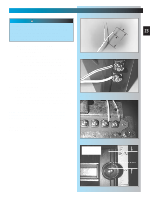
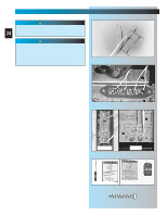
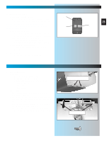
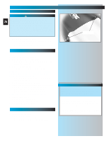
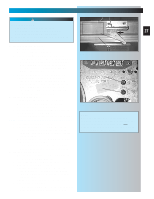
SECT 6-CONNECTING POWER WITH GROUNDED PLUG: WARNING To reduce the risk of electrical shock, this 26 equipment has a grounded type plug that includes a third (grounding) pin. This plug will only fit a grounded type outlet. If you do not have a grounded outlet, contact a qualified electrician to install one. DO NOT alter the plug in any way. The door operator must be properly grounded in order to prevent personal injury and damage to the components. 1. Check local building codes. • Does building code require permanent wiring? - If not, skip to step 9. - If yes, have an electrician perform steps 2 through 8. CONNECT POWER WITH PERMANENT WIRING Instructions for electrician. 2. Remove power from circuit. 3. Remove motor cover (Fig. 6-1). • Remove 4 screws [41] from cover and slide off back of power head. 4. Remove and discard power cord. • Cut off power cord inside power head. NOTE: There must be at least 6 inches of black and white wire inside the power head (Between splice and entrance bushing). • Remove and throw away power cord, strain relief and knock-out. 5. Install suitable entrance bushing. 6. Connect permanent wiring to power head wires. • Connect white supply line to white wire. • Connect black supply line to black wire. • Connect ground to green wire (ground). NOTE: Use only U.L. recognized wire nuts 7. Replace motor cover. • Slide motor cover back on. • Replace and tighten 4 screws. 8. Reconnect power to circuit. CONNECT POWER WITH PLUG 9. Plug in door operator. • See warning above. • Plug door operator into a grounded outlet. • Perform STB® alignment check (Fig. 6-2). FOR HELP-1.800.354.3643 OR GENIECOMPANY.COM Fig. 6-1 screws Safe-T-Beam® Alignment Check After turning the electrical power on, if the STBs are not in proper alignment, the red LED (Source) will blink continuously. To correct the problem - the brackets are flexible and can be adjusted slightly to bring the system into alignment. When the STBs are in alignment the red LED will stop blinking and stay on. Fig. 6-2
-
 1
1 -
2
-
3
-
4
-
5
-
6
-
7
-
8
-
9
-
10
-
11
-
12
-
13
-
14
-
15
-
16
-
17
-
18
-
19
-
20
-
 21
21 -
 22
22 -
 23
23 -
 24
24 -
 25
25 -
 26
26 -
 27
27 -
 28
28 -
 29
29 -
 30
30 -
 31
31 -
32
-
33
-
34
-
35
 |
 |
