Genie ScrewDrive Owner's Manual - Page 10
Open Blue Parts Bag
 |
View all Genie ScrewDrive manuals
Add to My Manuals
Save this manual to your list of manuals |
Page 10 highlights
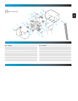
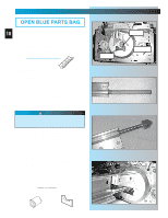
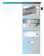
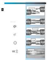
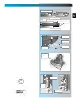
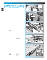
SECT 1-MAIN ASSEMBLY OPEN BLUE PARTS BAG NOTE: 3-piece rail assembly is for doors up to 10 and including 7 feet 6 inches high. An extension for 8 feet doors is available. 1. Set power head so that front panel (with end of shaft and rail attachment flange) is facing up. Fig. 1-1. NOTE: If you have this type Carriage Stop, skip Step 2. DO NOT install Bumber. FOR HELP-1.800.354.3643 OR GENIECOMPANY.COM bumper coupler serial no. 2. Install bumper [45]. • Peel protective paper from glue side of bumper. • Stick bumper into position as shown. Fig. 1-1. 3. Install coupler [39]. • Place coupler over end of shaft. • Turn it as needed until it engages with shaft. (It will drop down over end of shaft and will no longer turn freely. Fig. 1-1. 4. Set power head on its bottom. Fig. 1-4. CAUTION Drive screws can slide out of rail sections. Keep rail sections level until operator is fully assembled. 5. Attach 1-piece rail or "first" rail section[3A] of 3-piece rail to power head. • (3-piece only)Select "first" rail section. (It has protective cardboard sleeve over end of screw.) Fig. 1-2. • (3-piece only) Remove cardboard sleeve. • Slide end of screw out about 5 inches. Fig. 1-3. • Place bearing end of screw against coupler. Fig. 1-4. • Turn screw until it engages with coupler. • Slide rail section into rail attachment flange until holes in rail match up with holes in flange. • Secure "first" rail section with 2 bolts [4] and 2 nuts [5], hand tight only. Fig. 1-5. • For 1-piece rail, skip to step 8. [39] Coupler [45] Rubber bumper Fig. 1-1 Fig. 1-2 Fig. 1-3 Fig. 1-4
-
 1
1 -
2
-
3
-
4
-
 5
5 -
 6
6 -
 7
7 -
 8
8 -
 9
9 -
 10
10 -
 11
11 -
 12
12 -
 13
13 -
 14
14 -
 15
15 -
16
-
17
-
18
-
19
-
20
-
21
-
22
-
23
-
24
-
25
-
26
-
27
-
28
-
29
-
30
-
31
-
32
-
33
-
34
-
35
 |
 |
