Genie ScrewDrive Owner's Manual - Page 24
Sect 4-wall Control, Installation - screw drive
 |
View all Genie ScrewDrive manuals
Add to My Manuals
Save this manual to your list of manuals |
Page 24 highlights
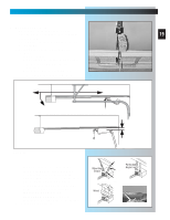
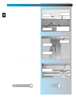
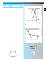
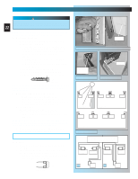
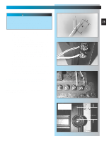
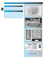
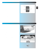
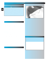
SECT 4-WALL CONTROL INSTALLATION FOR HELP- 1.800.354.3643 WARNING Power must be removed before attaching wires. 24 Be sure ends do not touch each other or other terminals. CAUTION • Use of any other wall control can cause the door to operate unexpectedly and the light not to work. • Cut or pinched wires can cause door operator to malfunction. Drive staples just tight enough to hold wire. 1. Run wire from power head to wall control • Find location for wall control: - In sight of door and away from moving parts. - At least 5 feet from floor, so small children cannot reach it. • Route wire from wall control to power head. • Use staples to fasten wire to ceiling and wall. NOTE: Use only staples included 2. Split wires at ends and remove 1/2 inch of insulation from end of each Wire. Fig. 4-1. 3. Attach wires to terminals. Fig. 4-2, Fig. 4-3. • Loosen (Do Not Remove) screws from Terminals at power head and wall control • Connect wires to power head - White wire to terminal # 1 - Striped wire to terminal #2 - Tighten screws • Connect wires to wall control - Striped wire to terminal "B" - White wire to terminal "W" - Tighten screws 4. Mount wall control. Fig. 4-4. • For Wall Console or Wall Button. - Use pan head screws [34]. 5. Mount entrapment warning label. Fig. 4-4. • Remove protective backing. • Stick label to wall next to wall control. - Tacks or staples may be required on some rough texture surfaces. NOTE: Additional wall controls are available from your dealer. ONLY ONE OF YOUR WALL CONTROLS MAY BE THE LIGHTED TYPE. If you have a lighted wall control, all your additional controls must be un-lighted. More than one lighted wall control per operator will cause a malfunction. Fig. 4-1 1/2" 1-1/4" to 1-1/2" Fig. 4-2 button Fig. 4-3 console Fig. 4-4 [34] #6 x 1-1/4" Pan head screw
-
 1
1 -
2
-
3
-
4
-
5
-
6
-
7
-
8
-
9
-
10
-
11
-
12
-
13
-
14
-
15
-
16
-
17
-
18
-
 19
19 -
 20
20 -
 21
21 -
 22
22 -
 23
23 -
 24
24 -
 25
25 -
 26
26 -
 27
27 -
 28
28 -
 29
29 -
30
-
31
-
32
-
33
-
34
-
35
 |
 |
