Genie ScrewDrive Owner's Manual - Page 11
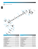
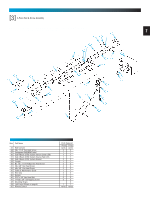
Main Assembly
 |
View all Genie ScrewDrive manuals
Add to My Manuals
Save this manual to your list of manuals |
Page 11 highlights
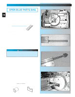
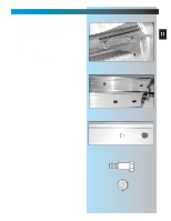
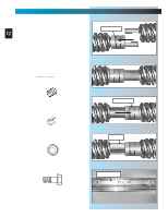
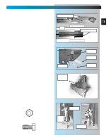
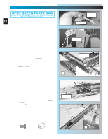
MAIN ASSEMBLY FOR HELP-1.800.354.3643 OR GENIECOMPANY.COM 6. Attach "middle" rail section [3B]. • Select "middle" rail section. (This section looks identical on both ends with each set of holes being about 4 inches apart.) Fig. 1-6. 11 • Find arrows stamped into side of rail. Fig. 1-7. • Align rail so arrows point away from power head. • Slide screw toward power head so it sticks out end of rail section about 2 inches. Fig. 1-5 middle rail section end rail section Fig. 1-6 Fig. 1-7 [4] 1/4" Shoulder bolt w/flange [5] 1/4" Flange nut
-
 1
1 -
2
-
3
-
4
-
5
-
 6
6 -
 7
7 -
 8
8 -
 9
9 -
 10
10 -
 11
11 -
 12
12 -
 13
13 -
 14
14 -
 15
15 -
 16
16 -
17
-
18
-
19
-
20
-
21
-
22
-
23
-
24
-
25
-
26
-
27
-
28
-
29
-
30
-
31
-
32
-
33
-
34
-
35
 |
 |

11
MAIN ASSEMBLY
FOR HELP-1.800.354.3643 OR GENIECOMPANY.COM
6.
Attach “middle” rail section
[3B]
.
•
Select “middle” rail section. (This section
looks identical on both ends with each set of
holes being about 4 inches apart.)
Fig. 1-6
.
•
Find arrows stamped into side of rail.
Fig. 1-7
.
•
Align rail so arrows point away from
power head.
•
Slide screw toward power head so it sticks
out end of rail section about 2 inches.
Fig. 1-5
Fig. 1-6
Fig. 1-7
1/4" Flange nut
1/4" Shoulder bolt w/flange
[4]
[5]
end rail section
middle rail section